![[Brads Electronic Projects]](https://bradsprojects.com/wp-content/uploads/2017/06/BPLogo1-240x58.png)
This game is based on the 1985 Nintendo classic – Super Mario Bros.
![]()
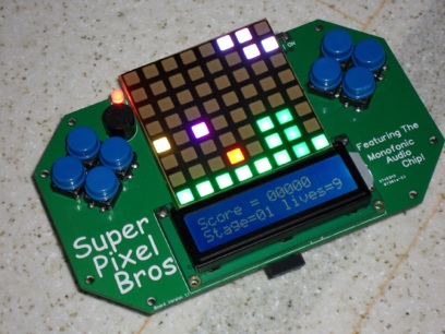
Super Mario Bros is one of my all time favourite games. I liked it so much in fact that I decided to make my own version, but restricting the graphics to just 64 pixels! I have given it the name ”Super Pixel Bros”
The game shares some similarities with the original, you just need to use your imagination since all the characters are represented by a single pixel. The aim of the game is to make your way through each of the twenty levels, jumping over obstacles, shooting and jumping on bad guys and avoiding pitfalls like lava, water and holes. It is an action packed game full of mayhem that is actually fun to play and even presents a bit of a challenge. A 16×2 LCD Screen is included for you to keep track of level, score and lives.
Sound FX and title music have been made possible by the Monofonic Audio Chip made by a good friend of mine and resident forum member S.Dudley – The Monofonic Audio Chip is a 1-bit sound FX chip that is ideal for a low resolution game such as this.
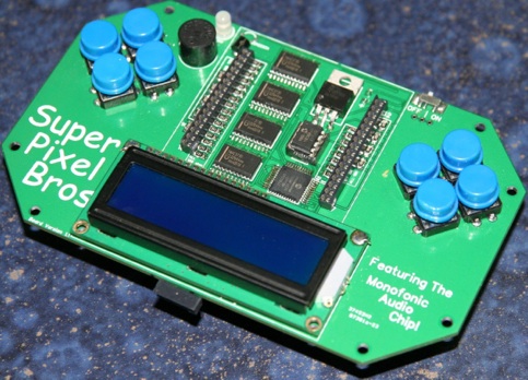
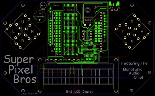
The Circuit Board.
While my original version was made using an electronics breadboard and through-hole components, I thought it would be much better to design a dedicated circuit board and keep it all as compact and cost effective as possible. As such i came up with a design similar to a handheld game system from the 1990’s. It consists of the 8×8 LED Matrix, eight game buttons, a speaker for sound, an LCD display and a handful of components to make the thing work.
You can purchase the PCB direct from iteadstudio by clicking here.
Youtube Video.
Of course the best way that I can show you the game in action is by way of a video clip. Just press play on the youtube video below.
Level Editor.
With the first release of the source code – there are 20 levels programmed in. I have tried to replicate the levels from the original Super Mario Bros as close as possible by using the level maps from here:
http://ian-albert.com/games/super_mario_bros_maps/
(Thanks to Ian Albert for those)
Each level is 120 pixels wide and can be quickly drawn up in paint and then converted to binary data using the level converter software that I made using Visual Basic.
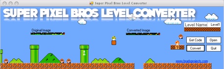
(Download link provided at the bottom of the page).
Please note that in order to program your newly created levels into the microcontroller to play them, you will require the full version of Swordfish Basic. (the free version does not allow you to use as much RAM required by the game unfortunately.)
However, if anyone would like to send me their levels (A complete set of 20 levels) I will be happy to compile it and put it on this web page for download.
Parts List.
- 1 x Super Pixel Bros Circuit Board (From iteadstudio)
- 1 x Common Anode 8×8 RGB LED Matrix
- 1 x 16 Character x 2 Line LCD Screen
- 1 x PIC18f4550 Surface Mount Microcontroller
- 1 x Monofonic Audio Chip
- 1 x 9Volt Battery Holder
- 1 x 9Volt Battery
- 1 x 7805 5Volt Regulator
- 1 x Mini Slide Switch OR 3 pin Header (to act as an on / off switch)
- 1 x 5mm Red Led
- 1 x PCB Mount Speaker
- 1 x 2n2222a NPN Transistor
- 1 x 32 pin IC Socket (Cut it in half to act as a mount for the LED Matrix)
- 4 x Surface Mount 74373 IC’s
- 2 x 1K Ohm Surface Mount Resistors
- 24 x 150 Ohm Surface Mount Resistors
- 9 x 10K Ohm Surface Mount Resistors
- 8 x PCB Mount Momentary Push Buttons
Construction.
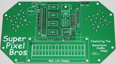
Construction of the project is more or less, quite straight forward. I have designed the board such that all components are labeled directly on the board which makes it very easy to determine what goes where.
Having said that, most of the components are surface mount which can be a bit tricky to solder in if you have not had experience with them before. If you have not, I would highly recommend getting yourself a soldering iron with a fine tip, some flux, some fine solder. On top of that – there are plenty of how to video’s and web pages that detail how to actually solder surface mount devices.
Some things to note.
- Make sure that you line the little dot on the microcontroller up with the little dot printed on the circuit board (the dot’s are located in one of the four corners).
- Make sure you install the 74373 chips, monofonic audio chip, transistor and the regulator the correct way around – just line them up with the outline printed on the circuit board and you should be fine.
- The buttons will actually fit in two different ways (180 degrees apart) but which ever way you put them in, they will work.
- The LED Matrix will also fit in two different ways however it will only work one way. All you need to do is guess which way to put it in (there’s a 50% chance you will get it correct) if it works then it’s all good! If it does not work, just take it out, rotate it 180 degrees and push it back in. It should be working fine now.
- I realise that not everyone will be able to get the on off switch that I bought so I also included another way to turn it on and off by using an easy to find three pin header. Either one will work as an on / off switch.
- The 9Volt battery connects to the + and – connections near the 7805 regulator
- I have included eight holes for a possible mounting point for a perspex case to house the circuit board. Maybe someone will make one?
- You may want to solder a 5Pin Header underneath the board to the ICSP Port although this isn’t necessary because you only really need to program it once.
Schematic and PCB Layout.
Unfortunately I have not actually drawn up a schematic for this project. I am quite busy these days and do not have any plans for drawing a schematic. I basically designed the circuit straight onto breadboard and once it was working, I then drew up the PCB design.
Please note that the PCB Design is in gerber format and you will need a gerber viewer to view them.
You are most welcome to draw up a schematic yourself from the circuit board design but I don’t see much point in now drawing up a schematic because this circuit board is dirt cheap and fits the purpose nicely.

How the Circuit Works.
Power is supplied via the 9Volt battery and dropped down and regulated at 5Volts (required by the digital circuits) by the 7805 regulator.
The circuit is all based around the PIC 18f4550 microcontroller which has been my microcontroller of choice for over a year now. They are inexpensive, have plenty of input / output ports, RAM, program memory and even some ROM which comes in handy when saving high scores.
Helping out with the graphics on the 8×8 Matrix are four 74373 chips which each contain eight data flip flops and eight tri-state buffers on their outputs. Basically the screen is drawn one column at a time (for a total of eight columns) all four of the 74373’s are connected to an eight bit port of the microcontroller (which effectively acts as a data bus) to draw one complete frame, the microcontroller will send out eight bits of red data and will save it to the red 74373. It will then send out eight bits of green data and save it to the green 74373, it will then send out eight bits of blue data and save it to the blue 74373. Once all three Color 74373’s have their data, we will send eight bits to the fourth 74373 and this will determine which column will actually display this data.
Once all four chips have their memory stored within them, the microcontroller will enable the tri-state buffers within the 74373’s which will send the data to the LED matrix and will light up certain Red Green and Blue segments in one particular column. the microcontroller repeats this process seven more times to complete one full picture. This happens many times a second so to the human eye, it looks like a steady picture.
Throughout this process, the microcontroller is constantly checking the game buttons to determine if one or more has been pressed. If it has, it will call a specific sub routine within the program memory to update the display in the required fashion (I.E. move the graphics left or right, or make the player jump or shoot etc…) The microcontroller will also send certain data to the Monofonic Audio Chip to tell it to play the required sound.
The Microcontroller also sends out specific data to the LCD screen to update it with specific information such as the players score, lives remaining and current level.
Source Code and Hex File.
The sourcecode has been written in Swordfish Basic. There is a free version available although the free version limits you to using only 256 Bytes of RAM (which is quite a lot) although it unfortunately is not enough for the Super Pixel Bros game (which requires 632 bytes). This means that you should be able to open and view the sourcecode with the free version, but not compile it. This is only really a problem for you if you for some reason want to modify the code.
Please note that the source code is messy and for the most part, it is not commented. I am providing it as is without warranty etc…
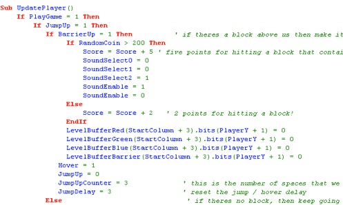
If all you want is to play the game as I have made it, then all you need is the HEX file (see below for download), which you will program straight to your microcontroller, no compiler is necessary.
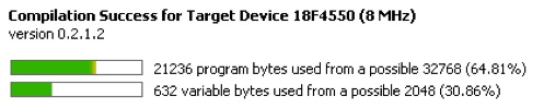
For those interested, the sourcecode takes up 1,173 lines of code, 21,236 bytes of program memory and requires 632 bytes of SRAM.
You can download the Super Pixel Bros Archive Here:


As a long time fan of SMB and Intellivision, stumbled across this project. Amazing! Kudos and thanks for sharing with the community!
wow that’s dope
[…] So a few years ago I decided to make my own version of this Nintendo classic but restrict it to just 64 pixels on an 8pixel X 8pixel RGB LED matrix. I gave it the name Super Pixel Bros. (Full details of this project can be found HERE) […]
[…] https://www.bradsprojects.com/super-pixel-bros/ […]
Sorry Jake, I meant to reply to you over a month ago but have just remembered now! You’re right I could have made a more detailed bill of materials, apologies for that. However itead studio was selling them as a kit with all required parts although I am unsure if they are still doing this. Kieran, I am unsure if itead is selling the kits still (I was not making any money from the kits, they just asked if they could do it) you may be interested though in my latest kickstarter campaign which you could make Super Pixel Bros… Read more »
On The Itead Studio page it says: Brad Slattery has build these interesting gadgets, and now we are working with him to have these made available as a kit (with all components included) so that you don’t have to shop around yourself.
I was just wandering if you are still doing this.
Thanks
Kieran
wish you more specific on the parts needed i cant find them all at the iteadstore, why cant you just make a kit!!!!!!
you like making things difficult for consumers dont you…
[…] Please note, This game system has been superseded by the new Super Pixel Bros handheld game system. You can find details of this game HERE. […]