![[Brads Electronic Projects]](https://bradsprojects.com/wp-content/uploads/2017/06/BPLogo1-240x58.png)
This was my first attempt at an RGB LED POV Display. POV stands for persistence of vision. This type of project works with our eyes relatively ‘slow’ refresh rate. When we flash some LED’s with certain information and then spin those LED’s, our eyes don’t see the fast flashes, but rather sees a complete picture ‘drawn’ in the air.
The circuit uses just 8 RGB leds which are mounted vertically and when spun horizontally it gives the illusion of having an 8×85 pixel display.
Youtube Video’s
This video shows my very first demonstration of the display. You will notice that the image constantly rotates around – this is because I have not incorporated a position sensor yet.
This video does have a position sensor and shows the animation capabilities of the display.
This video also has a position sensor and just shows a basic animation of a Super Mario Kart character – Toad.
Photo’s
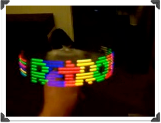
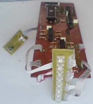
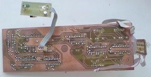
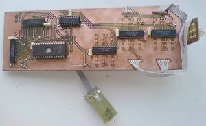
Here are a few photos of my original design (without a position sensor)
This first photo shows the display on but not yet spinning.

The second photo shows the display on and starting to spin.

This third photo shows the display on and spinning at full speed – thus creating an image in the air.
How it works.
The drawing process is really quite simple.
The pic microcontroller puts 00000000 00000000 on the eeproms address bus (selects the first address) This byte of info (at that address) is now placed on the data bus and all RED, GREEN, BLUE 74373’s are connected to this data bus. We only want red to grab this first byte of data so the microcontroller enables the red latch then closes it which means we have saved that byte to the RED 74373. Then it increments to the next address an latches that byte to the GREEN 74373 and then we increment to the next address then latch it to the BLUE 74373.
Now that all 74373’s have their data – the microcontroller then enables their outputs which sends the data to the LEDS. so we have just displayed one column (of the 85 per frame) So these leds will stay on for just a fraction of a second then turn off and we repeat the process to draw the next column and keep doing this untill one whole frame is drawn (85 columns).
The key thing to remember here is that it always follows the sequence RED, then GREEN then BLUE.
Lets do some math – if it takes 1 byte of red, 1 byte of green and one byte of blue per column then it is 3 bytes or 24 bits per column – then if there are 85 columns per frame that means that there is 3×85 = 255 bytes per frame or 2040bits per frame. If we use a 27E512 EEPROM then this holds 64kbytes which means 64k / 255 = approximately 255 frames. This means we can cycle through frames to make animations! See the next videos for examples of this.
I have also added a sensor to it so it knows when to start drawing each frame (without the sensor the project is subject to drifting (i.e the display does not stay in the one place no matter how much you try to adjust the motor speed) You can see the difference between having a sensor and not having a sensor in my youtube videos. The RETROBRAD logo has no sensor and therefor keeps drifting, but the other videos do have the sensor and therefor remain in the one position. The sensor is made of an IR LED shining straight into a photo diode. When there is nothing interrupting the signal, the photo diode has max current and therefor drops max voltage across it’s resistor. This means that the npn transistor connected to it will saturate and therefor send a logic 0 to the microcontroller. But when the sensor passes the nail (so it interupts the light beam, the photo-diodes current decreases causes the voltage of the resistor to decrease and therefor turns off the transistor – this then sends out a logic 1 to the microcontroller to say that we’ve passed the check-point and to start drawing the next frame – See the schematic for more information.
Power Transfer.
(See my 32×64 POV display to see how i managed to transfer power to the spinning board)
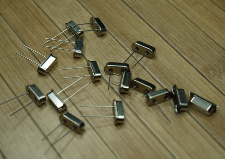
I have been asked by a number of people – “How do you mount the board to the motor?” we’ll here is the answer for you all!
I bought a pack of electrical termination screw connectors from a hardware store which cost just a few dollars. The first photo shows you one straight out of the packet.
The second photo shows it taken out of the plastic housing.

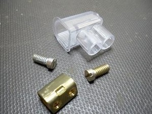
I used a file to rough up one end of the shaft. then I soldered this to the underside of my circuit board so that it was secure. then i screwed the two grub screws back in, and then you can put the motor shaft inside this metal casing and then tighten the two grub screws to hold it in place. And that’s it! that’s how you mount your circuit board to the motor.
The PCB Design
Unfortunately I lost my original PCB layout files when I upgraded my laptop. BUT Dai Omie has been very kind to share his own version of the 8×85 PCB layout files. and you can download all you need to know in this archive. (download at the bottom of page).
And here are some images of his completed project. Very professional!

The Source Code.
Things to note in the source code
- You can easily define how many frames of animation are in your animation loop by changing the total_frames variable to how ever many frames you have. The flying animation example has 178 frames. If you only have one steady picture or frame, simply put in the number 1.
- You can change the speed at which the animation runs by changing the frame_counter variable. (the higher the number, the more times each frame repeats itself therefor the SLOWER the animation speed.
- You can change the number of horizontal pixels by changing the pixel_counter variable. I set it to 85 because it is just about the perfect number for if we had an 8-bit address bus (which we sort of have with the microcontroller and with the help of the 74373’s we convert it to a 16-bit data bus.) So to draw each frame we need (1 byte of red x 85) + (1 byte of green x 85) + (1 byte of blue x 85) this comes to 255bytes which is basically the limit for an 8-bit address bus. So i use the lower 8-bit address lines as my frame data, and then the upper 8-bit address lines as my frame counter. this gives me a total of upto 255 frames of animation.
I have uploaded a Youtube video showing you how to use this excel spreadsheet to draw your own pictures and animations.
I hope it helps!
Conversion Software.
I had a friend do up an excel spreadsheet to make it easier to draw the pictures and animations to use on the display. You can download the spreadsheet file at the bottom of this page, you will also need a hex editor program I thoroughly recommend HxD – it is free and is just so easy to use.
If you wish to download/donate to HxD you can visit their page here
NOTE
You will require microsoft excel or a compatible spreadsheet program to use the painter. You will also need to make sure that you have a couple of addins enabled or the spreadsheet will not work! Here’s how to check that you have them installed:
Open Excel and click on the ‘tools’ menu item and then click on add-ins.
You then need to make sure that VBA additions are selected.
From here, you have three sheets – INPUT – WORKING – OUTPUT. You have your eight colours at the top left of screen, to draw a picture you need to copy and paste whatever colour you want, from the pallette into the 8×85 working area of the screen. You don’t have to paste one square at a time, but you can select multiple squares and paste at the one time. once your picture is drawn, you then click on the OUTPUT sheet, Then copy all of the hex numbers underneath “Copy and paste this next line into the hex editor” You then paste this data into you hex editor and then save it. Then open the file in your programmer software and write the hex file to you eeprom.
That is a really quick runthrough but i will upload a youtube video showing you exactly how to do it, including animations. If you have any problems you can always post in the forum.
And Finally, the parts list.
Parts List
- 8x Common Cathode RGB LEDS (5mm)
- 1x 16f648a or 16f628a microcontroller
- 5x 74373 tri-state buffers / latches
- 1x 27C512 / 27E512 EPROM / EEPROM
- 1x IR LED
- 1x Photo Diode
- 1x 2n2222 NPN Transistor
- 24x 100 ohm resistors
- 4x 10k resistors
- 1x DC motor
You can download all details to make your own 8×85 POV display here:


your file(schematic, photo,wearing) project is can’t to open. can shared ur new file please
what speed of servo ?
where this code ?
thanks so much if u reply my question 😀
I gathered scheme, but I can not sew .I can not compile the file. Can you help me? Put the compiled code here, please.
5 volts ? 7 volts? 10 volts? 12 volts ?
You will need 5volts to run everything on the board. You can use a 7805 voltage regulator to get you your 5volts (if your power supply is not 5v)
thanks you
help…
I gathered scheme, but I can not sew .I can not compile the file. Can you help me? Put the compiled code here, please.
How have you tried to compile the code? It’s not very practical for me to post the compiled code because the code needs to line up with how many frames of animation that you have stored in your eeprom.
single frame, static image
How many volts needed scheme? not specified anywhere! Tell me pleaseюю
I try to build your project, could you provide a more detailed description of the energy transfer to the board? Besides You say : “This method worked okay although I have since come up with a better method of transferring power to the board and you can see this in the new and improved one chip pov project.” Do you have a description of this method?
Hi Sergey, sorry I gave you the wrong link! Check out this one instead 🙂
http://www.instructables.com/id/The-One-Chip-Spinning-RGB-POV-Display-with-conve/step16/Getting-the-motor-base-together/
Quality content is the important to be a focus for the visitors to visit the web page, that’s
what this website is providing.
Need a larger one of these for my business… Maybe a few. Will you custom build them for us? Thanks.
Hi Sergey, have a look at this other project I made to get details of how to transfer power to the spinning board:
https://www.bradsprojects.com/32×64-pixel-spinning-rgb-pov-display/
how energy is transferred to the scheme?
Hi Сергей, I am not sure of the exact speed of the motor, it just needs to spin at around about 25 revolutions per second to make sure that you don’t get flicker.
What is the speed of the motor?
Hi Glenn, the yoututbe video for how to use the conversion video is on this very page (it is the video right near the bottom of this page.)
Hello sir, have you uploaded already the youtube-video-tutorial on image to excel?
Glenn