![[Brads Electronic Projects]](https://bradsprojects.com/wp-content/uploads/2017/06/BPLogo1-240x58.png)

The Digirule 2 is essentially an 8-bit programmable binary computer of the 1970’s – built into a 20cm ruler.
There are currently three different versions of the Digirule 2. More information on each version can be found in the links below:
Tindie
When I have stock, you can purchase a Digirule 2 from my Tindie store. Click on the Tindie image below to be taken to my store:

Kickstarter
The Digirule 2 was successfully funded on Kickstarter on the 28th of June 2018 where 487 backers pledged $22,097AUD. Kickstarter link HERE.
The Digirule 2A was successfully funded on Kickstarter on the 29th of May 2019 (which only ran for 48 hours) where 149 backers pledged $6,149AUD. Kickstarter link HERE.
The Digirule 2U was successfully funded on Kickstarter on the 17th of September 2020 where 629 backers pledged $38,849AUD. Kickstarter link HERE.
Digirule 2
The Digirule 2 is essentially an 8-bit binary computer of the 1970’s, built into a 20cm ruler. It features an 8-bit address bus, 8-bit data bus, data input buttons and 33 instructions for you to code your own programs.


Digirule 2 – Instruction Set
With an instruction set consisting of 33 instructions – the Digirule 2 can be programmed to perform all sorts of tasks, including fun games such as the classic ‘kill-the-bit’ game for the Altair 8800 or perhaps a Knightrider LED scanner, binary counter or a simple game of two player pong!
An excel spreadsheet allows you to easily write your code in mnemonic form – it will then automatically convert it into binary machine code for you to enter into the Digirule 2:

Digirule 2 – Features
- Dimensions 209mm x 40mm x 1.6mm
- 33 Instructions
- Open Source Hardware and Software
- Powered by an 8-bit Microchip PIC18F43K20 Microcontroller
- 256 Byte program memory space
- 8-bit data bus
- 8-bit address bus
- Eight blocks of 256 Byte flash memory to store your programs
- Eight address LED’s
- Eight Data LED’s
- Eight Data input buttons
Digirule 2 – Videos
Digirule 2 Preview
Getting Started With the Digirule 2
Digirule 2 Downloads
The following ZIP file contains the Bill of Materials, schematic, source code, PCB layout and Gerber files, User Manual, firmware and Excel Code maker for both the Digirule 2 and Digirule 2A:
Digirule 2 and 2A Files (8627 downloads )Digirule 2A
The Digirule 2A is essentially an 8-bit binary computer of the 1970’s, built into a 20cm PCB ruler. It features an 8-bit address bus, 8-bit data bus, eight data input buttons and 35 instructions for you to code your own programs. You will notice the Digirule 2A is virtually identical to the Digirule 2. The only differences being the extra two instructions printed on the rear of the device and the RUN/STOP LED’s being positioned below the switch in the 2A version. The major difference between the Digirule 2 and the Digirule 2A is in the firmware. The updated firmware has been re-written from scratch in C instead of Basic – by Brent Hauser (who is now the second member of the Digirule 2 team!).

Digirule 2A – Instruction Set
With an instruction set consisting of 35 instructions – the Digirule 2A can be programmed to perform all sorts of tasks, including fun games such as ‘kill-the-bit’ which was made famous on the Altair 8800 or perhaps a Knightrider LED scanner, binary counter or binary calculator.
An Excel spreadsheet allows you to easily write your code in mnemonic form – it will then automatically convert it into binary machine code for you to enter into the Digirule 2A:
Digirule 2A Excel Coder
Digirule 2A – Features
- Dimensions 209mm x 40mm x 1.6mm
- 35 Instructions
- Open Source Hardware and Software
- Powered by an 8-bit Microchip PIC18F45K20 Microcontroller
- 256 Byte program memory space (four bytes are reserved)
- 8-bit data bus
- 8-bit address bus
- Eight blocks of 256 Byte flash memory to save your programs
- Eight address LED’s
- Eight Data LED’s
- Eight Data input buttons
- CR2032 battery is not included due to shipping restrictions
Digirule 2A – Videos
Kit soldering instructional video. This video will give those who have bought the Digirule 2A (or 1A) kit a few tips on how to solder their kit together:
Digirule 2A Kit Soldering Tutorial
Digirule 2A – Downloads
The download below features the Digirule 2 and 2A sourcecode, schematic, PCB design, gerber, user manual and excel spreadsheet coder and also the soldering kit instructions. A big thank you to Brent Hauser for his updated Digirule 2A firmware!
Digirule 2 and 2A Files (8627 downloads )Digirule 2U
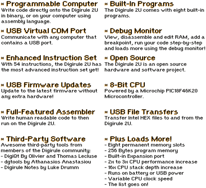
The Digirule 2U is basically an 8-bit programmable computer from the 1970’s, built into a 20cm Ruler. You can program binary code directly into the Digirule 2U using the push buttons and LED’s or you can write programs in assembly language on your computer then download them to the Digirule 2U via USB.
The Digirule 2U is the most feature-rich version of the Digirule to date. With 54 instructions, USB support, built-in serial debug monitor, full-featured assembler, 8-bit address bus, 8-bit data bus, eight 256-byte permanent memory slots and loads more.
With the Digirule 2U – You can discover the fascinating world of programming a computer in the actual language that the computer understands – binary!
You can code your own LED games, perform calculations, send and receive data to/from a computer or even another Digirule 2U. Each Digirule 2U comes pre-loaded with eight programs including ‘Hello World’, ‘Mastermind’ and ‘Prime Number Calculator’. The Digirule 2U features eight permanent memory locations where you can store your own awesome programs.
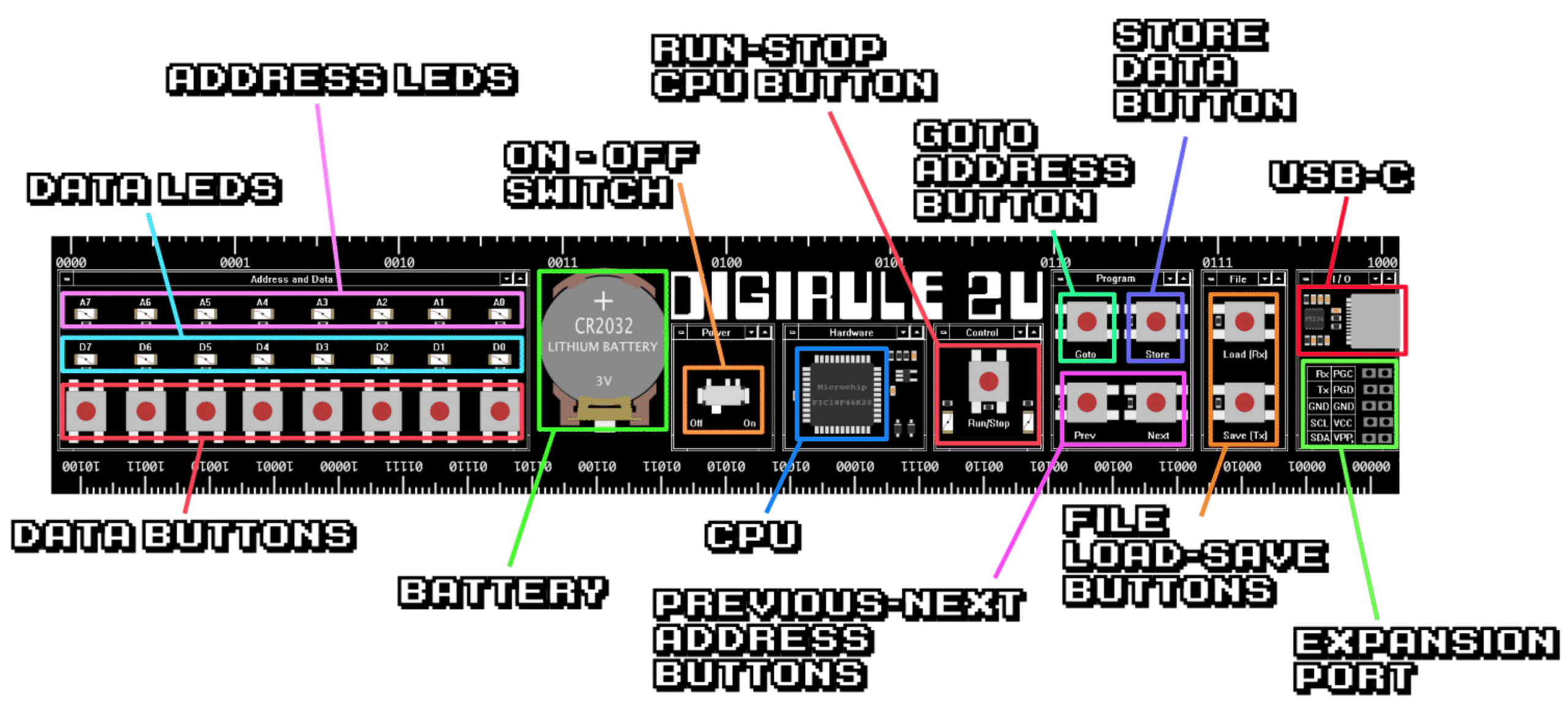
Digirule 2U – Features
Digirule 2U – Hardware
All the hardware that makes up this awesome 8-bit computer is built into the Digirule 2U PCB.
Digirule 2U – Instruction Set
With an instruction set consisting of 54 instructions – you can write some awesome programs!
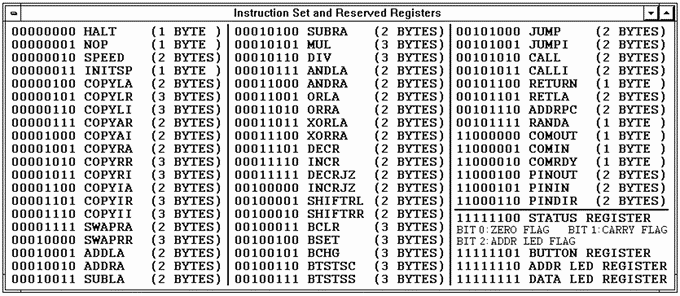
Digirule 2U Instruction Set
Digirule 2U – Debug Monitor
A feature-rich serial debug monitor is built into the Digirule 2U firmware. Simply plug the Digirule 2U into your USB port, load up your favourite serial terminal and start hacking into your Digirule 2U programs with your computer keyboard!

Digirule 2U Debug Monitor
Digirule 2U – Assembler
Write your Digirule 2U programs in assembly language then assemble them using the powerful Digirule 2U assembler!
Digirule 2U Assembler
Digirule 2U – USB Firmware Updater
The Digirule 2U has a built-in firmware updater allowing you to update the firmware without any extra hardware or programmer!

Digirule 2U USB Firmware Updater
Digirule 2U – Software Tools
The Digirule 2U features a set of command line tools including the Digirule 2U assembler and firmware updater, for macOS, Windows and Linux operating systems.

Digirule 2U – Videos
Digirule 2U Advertisement (Are you keeping up with the Digirule?)
Digirule 2U Walkthrough
Digirule 2U – Team
The Digirule 2U hardware was designed by Bradley Slattery (bradsprojects) and Brent Hauser (kd0gls). The Digirule 2U firmware and software tools including adr2 assembler, udr2 firmware updater and dldr2 file downloader were all developed by kd0gls. The sample programs that are built-in to the Digirule 2U were developed by kd0gls and Olivier Lecluse.
We were both helped out greatly by Olivier Lecluse via the Digirule 2U Discord server. Olivier has made all sorts of great sample programs for use on the Digirule 2U as well as a bunch of cool software tools that have been made for the Digirule 2U.
Digirule 2U – Third Party Tools
The Digirule 2 community has been around for a couple of years now and there have been some awesome third party tools developed for the Digirule 2 platform.
Olivier and Thomas Lecluse have developed an amazing GUI based Digirule 2 development environment written in Python named DigiQt.
Athanasios Anastasiou has come up with a great set of Digirule 2 development tools written in Python named dgtools.
Luke Drumm has made a fantastic online assembler and basic interpreter for the Digirule 2U named digirulenotes.
Chris Perrod has taken what Luke Drumm has made and made it even better by allowing you to run a real-time simulation of the Address and Data LEDs. Check out the link HERE.
Digirule 2U – Downloads
You can find downloads for the Digirule 2U including user manual, schematic, sourcecode, PCB design files, Bill of Materials, firmware and more at the Digirule 2U GitHub Repo HERE.
You can check out the online version of the Digirule 2U User Manuals in the links below:
- Digirule 2U User Manual
- adr2 User Manual (Digirule 2U Assembler)
- dldr2 User Manual (Digirule 2U downloader utility which is required by macOS users)
- udr2 USer Manual (Digirule 2U firmware updater)
Links
The Digirule 2 line of programmable computers has seen a nice little community create their own assemblers, compilers and programs for the Digirule 2, 2A and 2U.
Olivier Lecluse and his son Thomas created a feature-rich Digirule 2, 2A and 2U simulator called ‘DigiQt’. It is with great sadness that I mention that Olivier passed away just after he released DigiQt. Olivier was a very active member of the Digirule 2 community and his presence will be sorely missed. You can find DigiQt HERE.
Luke Drumm has made a fantastic Digirule 2/2A Assembler and can be found HERE.
Luke has also made a Basic Compiler which can be found HERE.
User Uploads
If you’ve made a program that you’d like to share with others, feel free to upload it using the form below:
You can browse the user upload directory by clicking HERE.


ADDRA and SUBRA seem to behave exactly like ADDLA and SUBLA. Is this a potential issue or a misinterpretation?
[…] Digirule2: https://bradsprojects.com/digirule2/ […]
I see the tindie store is out of stock. How can I get one?
Is it very difficult to make my own? I am a programmer that enjoys enjoys reading electronics and computer science books like The Art Of Electronics and Elements Of Computing Systems.
@Brad did you solder them one by one? How did you assemble the items in the Bill of Materials?
Based on the great job done by Luke Drumm ( who allowed the hack, thank you Luke ! ), a real-time version of his Digirulenotes, coded for teaching purposes :
http://193.49.249.136:20180/~web/premiere2/Digirule_JS_Simulator/Digirule_Notes.html
(Don’t be scared by the IP, it’s an academic server, no domain name 😉
2U arrived fully assembled! (I was almost looking forward to the solder party)
Couldn’t upload my countdown timer, so I’ve githubbed it. First program written in assembly, makes me happy. https://github.com/TroyFletcher/Digirule_countdown_timer
v1.0 of the Digimulator project is out : https://github.com/profjahier/digimulator/. With the new editor, writing programs for the digirule is so easy
Fantastic work Olivier! I’m off to check it out right now 🙂
Following the notes from Athanasios Anastasiou (https://dgtools.readthedocs.io/en/latest/instruction_set_notes.html) about the digirule instructions set, I have added some new instructions to the digirule.
I made a custom firmware and uploaded it on my digirule (a pickit device is needed). This is so cool to be able to add new instruction to our CPU !
If you can’t flash your device, you can still test these new instruction on the digimulator (https://github.com/profjahier/digimulator/).
All the details, firmware source and instructions usage are described here :
https://github.com/wawachief/DGR2B
These look like so much fun to use!
Will they ever be back in stock?
I will eventually get another batch made – but this will have to wait until I find some free time 🙂
Just got mine…wow, is it awesome!
Only took a couple hours to solder up. I spent last evening puzzling over the instructions on the back and messing around. Absolutely fantastic device!
10/10 will “waste” a lot of my time.
I have uploaded a little program for the digirule to perform multiplication using the russian (or egyptian) method as explained in this @numberphile video : https://youtu.be/HJ_PP5rqLg0
– mult.txt is the simplest one : the two numbers are hard-coded into the program
– mult2.txt is a bit more sophisticated as the numbers are typed by the user using an Input subroutine By Jaap Scherphuis from the add program.
Here is a little demonstration using the digirule simulator : (Click the image below to show the animation).
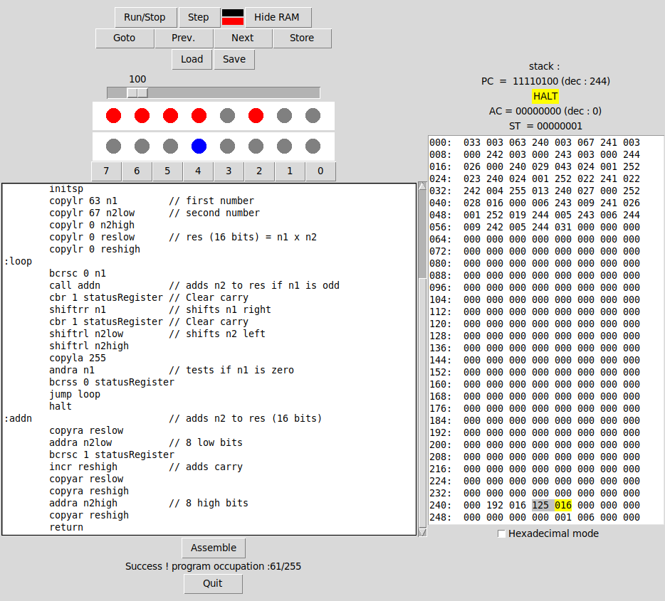
Fantastic job once again Olivier! I love watching the contents of RAM update as the program is running through the multiplication process. Well done and thanks for sharing!
which typ of processor is simulated there?
Hi Micha-uhl. It isn’t simulating any particular type of processor. It has its own unique instruction set.
Hi Brad
a photograph of my computer class students using Digirule…a great success, some of them now want to buy one ( so bad they’re out of stock…)
Thank you so much again for having made hard things much more playful
Chris
Always great to see people making good use of my projects. I certainly hope they have fun using them. Now that it is the new year, perhaps I should have another batch of them made so people can buy them again 🙂
Thanks very much for posting the photo of your students!
Excellent 🙂 Quel type d’activités leur proposes-tu ?
Digirule Simulator :
Ronan Jahier and I wrote a little simulator for the digirule in Python :
https://github.com/profjahier/digimulator
It features
– a step by step execution with a complete view of the ram
– an embedded assembler with the same syntax as digirulenotes.com
– a basic Tk interface, easy to use.
The goal is to make the development of new programs for the digirule easier.
That looks amazing! Sorry for not seeing your post earlier however for some reason I have not been receiving notifications of new comments via email.
I absolutely love the interface – very 1990’s!
How long did it take the two of you to make this?
Is there a way to have this run from within a web browser?
Once again, very well done – I love your work!
Thank you. It took us about 6 days. It is written in python, this is not designed to work in a browser, but as a desktop application. We did it because we love your digirule and as teachers, we think it could be useful for student to learn how computers work at a very basic level. But we have two problems for that : we don’t have digirule for everyone, and programs are not easy to type in and debug. This simulator aims to solve these problems : as a desktop app, we can bring the digirule to each student,… Read more »
Hello,
Glad you like it ! We do too… 🙂
Well done to you too Ronan! Fantastic effort 🙂
I’d love to get you some more Digirule’s but unfortunately I am all out once again (and have been for a while now…)
If you would like to get some for your class just let me know and I can look at getting a batch made and give you a discount. Just let me know if you would like to do this.
Over the weekend I will have some time to sit down and try out your program. I will let you know how I go with it 🙂
Thank you for your offer. My collegue and I thought about making 10 digirules using Chris’s PCB. We have a local supplier able to do this, so we are OK. Don’t bother making a special batch for us.
We hope you will enjoy the emulator. Don’t hesitate to report issues or suggest improvements.
Bien joué Olivier ;-), très beau boulot, bravo !!!
[…] me suis, pour cette partie, inspiré du Digirule 2A. J’ai bien tenté d’en acheter un, mais c’est comme pour les billets pour la Hell […]
I have finished the building of the through hole version of the digirule using Chris Perrod’s gerber files and I am quite happy with the result. I am using a 18F45K20 PIC microcontroller. There is a few problems though with the PCB, but no big deal : 1. There is a missing pul-up on the GOTO button. I had to solder a wire on the back 2. The run and stop LEDs are swapped. I had to make some changes in the source code to make them work as expected (I changed the value of the RUN_LED variable). The STL… Read more »
Woo, nice !! But I was quite sure I updated the files as I obviously encountered the same issues..apparently not, sorry !
Great job !
They look amazing! I can’t believe I didn’t see this post earlier!
Did you need to use lower value resistors for the white and green LED’s? (since they have a higher forward voltage drop than the red LED’s).
thanks. It is Chris’s job that looks amazing. I used different resistors indeed for the white and green leds. I just tried on a breadboard different values until I see about the same brightness. I have 1k on the red ones and 3.3k on the other ones. I didn’t want them to be too bright.
I like this “big” item. Where can I find the files?
Michael
Greetings everyone! I’ve been reading with great interest all the activity going on here. At Brad’s suggestion, I’ll chime in with a few thoughts that will hopefully be of use to those of you attempting to get the code running on different hardware. While porting the Digirule 2A code to a different PIC device is certainly doable, there are several hardware-specific details that will need to be taken into account (see below). For those of you not interested in studying datasheets and altering code, may I suggest that your best bet is to stick with the specific part for which… Read more »
Hi. I am trying to build a digirule on a breadboard. I bought a PIC18F4520. I flashed the firmware with a tl866 programmer. At the beginning it seems to work as I have the flashing led animation but then it stops and nothing happens.
I am afraid that 18F4520 and 18F45K20 are not the same 🙁 I thought they were.
Is there a hex file that could work on 18f4520 ?
Have you tried recompiling the source code for the 18f4520?
Yes I did, but with no success yes : I can recompile the source for the 18f45k20 so I know the tools are working correctly, but it wont compile for the 18f4520 because registers are not the same : ANSEL, ANSELH, RBPU and WPUB do not exist on the 4520 so I have to figure out what they mean and their equivalent on the 4520. I have some experience with arduinos but I am totally new with PICs. I gess I have some datasheet reading ahead !
I managed to compile a hex file for the 18f4520 but I have the same issue 🙁 I wonder if the problem does not come from my tl866 programmer since I have problems to just blink an LED !
Perhaps you could read the code back from the microcontroller and compare the hex data to that of the .hex file. If it reads the data back faithfully then it would seem the programmer is just fine.
Do you have a supplier of 18F45k20 chips close by?
the programmer is fine, I can finally blink an led ! maybe the code modifications I had to make in order to compile for 18f4520 are incorrect, maybe the connexions on the breadboard are not good. I ordered 18f45k20 chips so I will know for sure !
Olivier, si tu veux, je peux jeter un oeil à ton code pour le 18F4520, j’ai déja adapté l’original pour le 18F4685 et le 18F45K22. Principalement, c’est le fichier de config qu’il faut changer, et entre le 18F4520 et le 18F45K22 il n’y a pas beaucoup de différences…
J’ai eu pas mal de soucis également à cause d’une broche du PIC qui n’était pas tirée au +5V, et j’avais exactement le même problème que toi : l’anim de début fonctionnait, puis plus rien…depuis que j’ai rajouté la connexion manquante, ça roule !
Bon courage
Merci de ta proposition, c’est vraiment très sympa de ta part. Comment puis-je t’envoyer mes 2 fichiers (config et main) ?
J’ai un peu modifié le code pour que ça compile sur le 18f4520 mais je ne suis pas sûr du tout de ce que j’ai fait ! En particulier, des options que j’ai du modifier qui touchent à des configurations de pullup… J’ai essayé les 2 .hex dans ton archive mais ça ne marche pas mieux.
J’ai vérifié les connexions et tout semble correct. Te rappelles-tu la broche que tu avais oublié et qui provoquait le même symptome ?
My problem seems to be linked with the RB5 port : It should be pulled up but I read 0V. On the other ports B, I read 5V as expected. When I force RB5 high with a 5K pull-up, the startup animation won’t start. When I pull RB5 down, the startup animation starts.
It seems that RB5 needs to be down for the program to start, I don’t understand why. Maybe a config problem.
Perhaps Brent Hauser might have an answer for you because the latest source code was developed by him. Since my reply here is a bit late – have you managed to make any progress since your last comment?
Nothing new. I received my 18f45k20 but I can’t program them with my tl866 so I ordered a pickit3…
Olivier,
RB5 is the Low-Voltage Programming (LVP) enable pin. Your PIC device is probably configured (through its configuration bits) to enable LVP. The default Digirule 2A firmware disables LVP because RB5 is being used for I/O. The standard High-Voltage Programming capabilities of the PICkit 3 are used instead.
Thank you for your answer, that makes perfect sense. Unfortunately I still can’t get RB5 to go high. I checked config.c : I have
#pragma config LVP = OFF
I tried to put it on and checked the hex files, they are different :
$ diff lvp1.hex lvp0.hex
484c484
:0E000000FF08901EFF0180FF0FC00FE00F40B1
so the LVP option is present in the hex file. Is there another place to look for this configuration ?
I don’t have a pickit yet so I am using an arduino to program the PIC. I don’t know if this could be an issue.
If I understand correctly, you have a PIC18F45K20 (DIP) on a breadboard. Are you using Brad’s exact circuit (but with adjustments for DIP pin numbers) ? Are you using the default (unmodified) firmware? If not, I recommend you revert to the default hardware and firmware configurations and get that working before modifying anything. If your config.c has LVP disabled then the problem could indeed be your programmer. Third-party programmers are known to have difficulties properly programming configuration bits, but that’s just a guess. Does your programmer use a 5-signal interface, and are they all connected to the proper pins (VPP… Read more »
One other thought just occurred. The Arduino ecosystem is outside my area of expertise, but many of the boards I’ve seen are based around 5V AVR devices. The PIC18F45K20 is strictly a 1V8 to 3V6 device and would almost certainly be destroyed by 5V power or 5V signals. Does your current programmer have the necessary level translation hardware to work with lower voltage devices? The PICkit 3 you’ve ordered will.
I don’t use a 18F45K20 but a 18F4520, I made a mistake when I ordered them, believing they were the same 🙁 The 18F4520 is 5V compliant, so no problem with signals from the arduino. I use Brad’s exact same circuit on a breadboard. I checked every connections with a multimeter. I had to change a few thing for the program to compile on 18f4520, maybe I did something wrong here. Here is the beginning of the main function : some of the 18f45K20 registers don’t exist on the 18f4520 ; OSCCONbits.IRCF = 0b110; LATA = 0b00000000; TRISA = 0b00000000;… Read more »
I tried to program the pic with a tl866ii selecting 18LF4520 and it worked. The RP5 pin is pulled-up, so the problem came definitively from the arduino programmer.
Unfortunately the PIC still stops just after the initial animation.
Olivier, Please make the following changes to main.c. Note that I have commented out the original lines of code (with //) but left them in place for reference. You may want to do likewise until you get everything running. // OSCCONbits.IRCF = 0b110; OSCCONbits.IRCF = 0b111; // ANSEL = 0b00000000; // ANSELH = 0b00000000; ADCON1 = 0b00001111; CMCON = 0b00000111; LATA = 0b00000000; TRISA = 0b00000000; LATB = 0b00000000; TRISB = 0b11111111; RBPU = 0; // WPUB = 0b11111111; LATC = 0b00000000; TRISC = 0b00110001; LATD = 0b00000000; TRISD = 0b00000000; LATE = 0b00000000; TRISE = 0b00001111; PR2 = 199;… Read more »
It WORKS !!! Thank you so much Brent, I missed the ADCON1 and CMCON initializations in the datasheet. I can play kill the bit on the breadboard 🙂
I loaded kill the bit with no problems. It seems that saving works too.
Great! Please check your TRISC bits too, as according to the code you posted here you have unused pin RC2 configured as an input when it should be an output (so it doesn’t float). I finished checking the flash read/write routines in file.c, and I think they’re compatible with the PIC18F4520 as-is.
Yes I fixed the RC2 pin, I did a test with it and forgot to put it back.
I typed in my 2-complement program and it works fine. I could save it and reload it, so I would say everything is working great. I will upload the hex file for the 18f4520 if someone is interested.
Also make sure that subtle change to your OSCCON IRCF bits gets made, otherwise you’ll be running slow at 4 MHz.
yes I did, the speed is the same as the original digirule.
Oups, désolé, ça faisait un moment que je n’étais plus venu sur le forum…je vois que tu as réglé ton problème avec l’aide de Brent Hauser..cool !!
En effet, il m’a bien dépanné. Il me manquait l’initialisation des registres ADCON1 et CMCON pour remplacer ANSEL et ANSELH. J’ai commandé les PCB selon ton schéma, je suis prêt à les recevoir maintenant 🙂
Cool ! Pour l’alim, je fais tourner maintenant mes Digirule avec une pile CR2032; même si les PICS sont des versions 5V, ça marche bien.
Hi, I’m having a great time programming my new DigiRule2a. Early days, but I got a thrill out of writing a program to multiply two numbers and display the result. I’d like to build my own DigiRule2a using through-hole components to make a rugged version for my grandsons, but I haven’t programmed a PIC in years. Could I use a PIC16F877? I have a few left over from an old project.
Thanks for a great product!
John
G4EDX
Simple ‘hello world’ programs are great fun whenever working with a new language or in this case – the Digirule2a 🙂 Very glad to hear your having fun with it! Chris Perrod has actually designed a through-hole version of the Digirule2a (scroll through the comments below to see what he has posted). He might be willing to release his Gerber files so everyone can use them to male their own boards – otherwise I will do a through-hole version design and then upload them for all to use. You could certainly use a PIC16F877 however this would require some tweaking… Read more »
Hi Brad, thank you very much for the reply. I have a PicsArt Plus programmer but this is quite old. It has an RS-232 interface and I don’t know whether it’s compatible with the PIC18f45k20. I expect modern programmers are much cheaper now.
I’ll most likely build my version on stripboard with big switches and LEDs coming through a front panel, so I don’t need Gerber files. I built a replica Cosmac Elf CDP1802 computer earlier this year on perfboard using wire-wrap sockets. That took me back a few decades!
I’ll look into programmers for the 18f45.
Best regards,
John
That should have been Picstart Plus of course!
I would highly recommend a PICKIT 3 or compatible programmer. Since Microchip release the schematics and firmware for the PICKIT 3 openly, there are many cheap clones that can be bought for $10 or less 🙂 Have a look at ebay or aliexpress to get one.
If your building your on stripboard – you should be all good to go with the schematic which you’ve probably found is included in the download in the link above.
Hello again Brad,
I’ve ordered three PIC18F45K20s which should arrive early next week. I think I know where I can borrow a PicKit 2 programmer. Failing that I’ll order a PicKit 3.
I don’t feel up to tweaking a C program. I’ve only ever programmed PICs in assembler, but since doing that I’ve spent some time on the Arduino so maybe I’m partway there.
I’ll let you know how my build goes. I may have questions too…
Best regards,
John
Be sure to ask any questions that you may have, the build should be quite straight forward (it is a pretty basic circuit as you’ve probably found). The firmware is all good to go so once you have your programmer – just make sure you have a breakout to the five required pins on the microcontroller so you can connect your programmer 🙂
Hi

I have uploaded a small program to compute the 2 complement of a number.
By browsing the files uploaded, I saw a through-hole version of the digirule :
Are the gerber files available ? Making the digirule by ourselves could be handy
Hi Olivier, I have only just noticed your comment here.
Thanks for the upload for the 2’s complement 🙂
The through-hole version you have found is the great work of Chris Perrod (if you scroll down this page you will see he has made some comments). I’ll ask him if he has his Gerber files available for all 🙂 Otherwise, I can draw up a through-hole version and upload the Gerber also 🙂
thank you for your answer. I have just received my PICs, I will try first a breadboard version. I will keep you informed.
Hi
what an idiot I’ve been, I could have posted earlier my work ( with HEX files for both 18F4685 and 18F45K22 ).
Have fun ( as I have !! )
Chris
Thank you. I don’t see the files. Where did you put them ?
OK I see them, thank you !
Hi Brad,
I managed 😁 to place my order on the 9th, you sent it “cheaply” on the 11th, and it arrived here in Canada 🇨🇦 on the 27th. Many thanks.
– –
Matt
Great to hear Matt, I hope you’re having loads of fun with it!
-teaser- Fascinated by the 70’s computers? So you have to get a 70’s game on it! What about a full Mastermind? Computer generates a 4-digits[0-7] number which you have to guess. For each of your guesses, the computer will tell you how many correctly placed digits and how many incorrectly placed digits you have by lightning up as many LED, 0 to 4 for each type. At the end, when you get the 4/0 final answer (4 correctly placed digits), you’ll see how many guesses you used. Just press a button and computer will be ready for another game! -/teaser-… Read more »
And of course I don’t know how to count… 249 bytes are used…
Code is coming soon.
This sounds fantastic! look forward to having a play of this one myself. Let us know when the code is available 🙂
Uploaded my mastermind!
User manual at the start of file. I tried to add lots of comments in the code but it may not be very easy to follow (self modifying code for example to access an array).
Have fun and let me know if there is any trouble with it.
I’ve also written my own assembler in Python with some different syntax.
Labels are followed by ‘:’, comments are started with ‘#’ (ok, cosmetic changes).
Constants are defined with the .DEF directive and storage can be reserved with .BYTE (associating a label with a storage address).
Code can be found on https://github.com/EmmanuelLazard/Digirule-2A along with the mastermind version for my assembler. Uploaded version here is for the online Drumm’s assembler
I am soooo impressed ! Your mastermind is impressive and fun to play with 🙂
This is fantastic Emmanuel! very nice work indeed!
This is by far the most impressive use of the Digirule 2 that I have seen 🙂
Hi Brad,
This project looks amazing and I want to build it myself! I’m new to microchips and I was wondering if you could explain to me how you programmed the code onto the chip, maybe in a video or just in descriptive words?
Thanks and keep up the great work!
Hi Sharlene – I apologise for the late reply. If you are new to electronics (microchips) then i’d recommend starting out with the basics first. The Digirule2 (and 2A) that you see on this page comes with the chip already programmed however to load the program onto the chip, you can simply use a PICKIT 3 (or similar programmer device). The PICKIT 3 plugs into the USB port of a computer and the other end connects to the programming pins of the Digirule 2. You then load the PICKIT software on your computer, open up the .hex file and copy… Read more »
Hello Brad,
Small mistake in documentation.
On the ruler, RETURN has code 30 and RETLA 31, whereas in the user manual, it’s the opposite (table on page 10 and page 49).
I’ve checked the source code and found that documentation is correct!
So you have to reprint the ruler for the next batch!
Thanks for picking up the error Emmanuel – i’ll be sure to fix it for the next batch and have also added a correction at the top of this page to let everyone know 🙂
I’ve uploaded a quintessential “Das Blinkenlights” for the Digirule 2A. There are many variations possible, but I like this one because it creates some variation in how long a LED is illuminated.
Curiously, if you run this with SPEED 0, and watch the A0 and D0 LEDs, you’ll discern that RANDA is not quite random, but yields numbers with their lower 3 bits zero in a rather “too regular” pattern.
Thanks for the upload Frank! When I get some time – i’ll program it into my Digirule 2A and check out the LED effects 🙂 Perhaps we can call RANDA – random-ish?
Hi Frank, The RANDA instruction provides a *pseudo* random number, not a truly random one. The implementation is relatively simple to remain in line with the 8-bit nature of the rest of the machine, and to hopefully provide a reasonable level of understandability to those who might study the code. When examined at the bit level you will definitely see a pattern as a result of the recirculating shift register used to implement the generator. However when examined as an entire number, things appear a bit more random. The generator has a period of 255, after which it will repeat… Read more »
Hi Brad, and many thanks for this project. I’m one of the lucky 50s that managed to order one Digirule yesterday during the 20mn window when they were available! While waiting for the ruler coming from down-under, I was playing with the code. One instruction I really think is missing is an indirect addressing mode. Something like COPYIA: copy a memory location in the accumulator; address is given by the previous content of the accumulator. It wouldn’t change the spirit of the project but would greatly improve programming capabilities. Without it, I’m struggling with self-modifying code to simulate the indirect… Read more »
Hi Emmanuel, that sounds like a handy addition. Do you have some sort of programmer (like a PICkit for instance) that you could update your own firmware with?
Unfortunately no…
Hi Brad, any update on when you’ll have Digirule2/2A in stock on Tindie? They went out of stock like 1 day before I was going to order a couple, just my luck! 🙂
They will be ready very soon! They have been delivered and I am now in the process of programming and testing them. Stay tuned!
[…] je me suis inspiré un peu de l’Altair, et beaucoup plus du « Digirule 2 » : quelques switches, une poignée de LEDs, et quelques artifices permettent […]
I received my DR2A more than a week ago, and spent most of that time trying to kill the battery running the 16-bit counter with speed set to 0. I got up to 53 hours, 45 minutes (intermittently) and gave up; the LEDs were so dim they were barely visible, the battery voltage was down to 1.7V, but the program churned on just fine! I measured the current while running that program (which keeps each LED on 50% of the time) and it averaged 15ma. The Energizer battery I was using was rated at 240mah (to 2V), so you can… Read more »
I’ve had the same experience with coin batteries. I’ve left them connected to a single LED without a resistor and they last for days, before finally going dead. And you’re right about battery usage with the Digirule – it will bring you many many hours of use before you need to replace the battery. 🙂
What criteria are sufficient for a “strong” password?
I can’t get past “medium”, and haven’t been able to register for your pages and Forum…
Sorry for the late reply Dave, I’m not sure what a strong password is. Perhaps it needs a lowercase, uppercase, number and symbol? The forum should be different – since that is a seperate login to the main site. I haven’t used the forum in quite some time however.
Just received my DR2A – nice piece of work; I love it!
I couldn’t find Luke Drumm’s assembler. Has it been removed?
It’s there on http://digirulenotes.com/. You can download the web page and run it locally.
The Code Maker Excel file is in the download zip file.
OK, I know I’m old and half-blind, but I just don’t see it there! You have buttons to the various example programs (very nice!), but I don’t see a link or anything for the Assembler.
WAIT! Oh, $hit! – that page IS the assembler! Forest, no trees…
Thanks
Sorry for the late reply. It seems you’ve found it now? If not here is the link 🙂
http://digirulenotes.com/
I did, thank you, Brad! It took me a while to realize the web page IS the assembler, and a nice emulator, to boot.
I do have another question, for you specifically:
What criteria are sufficient for a “strong” password?
I can’t get past “medium”, and haven’t been able to register for your pages and Forum…
I just got my Digirule2A and I put a battery in and it worked; well I was able to poke through all the memory addresses, so I put it away. I picked it up to do some more playing only to find that it won’t seem to turn on. I tried switching the battery and still no luck. Any quick things I can check.
Well some poking and prodding show that it works sometimes…and it has pulled my new 3v Energizer down to 2.6 or so in just a little use (entering the program from the video).
Sorry to hear you’re having problems Chris. From your first comment and your reply, it seems your Digirule 2 is drawing far too much current for whatever reason. I would be looking at the microcontroller chip to see if any of the legs have been soldered together. Also, when it is turned on – is the chip getting hot?
I see the issue….is there anyway to send a picture? there is a tab on the positive that is bent down touching the negative terminal of the battery. Dead short, most of the time! I bent it back and it seems to turn on consistently.
I see. That would explain it. Did you follow the battery installation instructions in the user manual? Because if you install the battery into the plastic tab end first and then push down – it will end up bending down the metal tab. The user manual shows that you need to install the battery in the metal tab end first and then push down on the plastic tab end to lock it in.
I’m not sure if I did it wrong at first; but it’s all good now. Thanks!
Ok great. Let me know if you have any other issues 🙂
I’ve got my Digirule2 recently and I’d like to make one suggestion. The Halt instruction right now just stops the running program and erases any data displayed on the LEDs. In my opinion this should behave more like a breakpoint by stopping the program preserving the state at that particular instruction. O further press on Run should then continue from where it was.
It sounds pretty straight forward to implement. Perhaps in addition to the halt instruction. Do you have a pickit or similar programmer to experiment with adding this new instruction?
Yes I have all kind of programmers. I’m not sure if I should modify the HALT instruction or add a new BRK one. I have just started looking at the code and I’ve recompiled Brent’s C code (with some 3 line changes) with the professional HiTech C compiler with all the optimizations turned on. The resulting firmware is half the size of the one compiled with MPLAB C (not that size or speed matters).
Zelea2, The HALT instruction simply stops the execution of instructions without losing any CPU or memory state information, as if the user had done so manually by pressing the Stop button. The PC is left pointing to the instruction immediately following the HALT, and you can resume execution from that point by pressing the Start button. The reason the Data LEDs change is because when the CPU stops you are now in the “edit” mode, so the Data LEDs are displaying the contents of memory at the location shown on the Address LEDs, instead of the contents of the Data… Read more »
Hi Brad,
I have just received the digirule 1A, and I think it does not have the update as when I try to select mode 10, 11 it will not allows me to select them, also the persistence of vision text does not display text.
Is there a way I can upgrade it myself?
Thank you
Valerio
Hi Valerio. The Digirule 1 and updated 1A both have the persistence of vision feature built into the bonus mode. Could you explain how you are trying to access the bonus modes?
Hi Brad,
I reloaded the firmware and all is well now.
I also discovered that mode 10 and 11 are not part of the of the firmware update.
Thanks for your prompt reply.
Hi Brad! Great tool you made here. I got my one yesterday. It took 15 days for shipping to the other side of the planet. I made a few tests and it works great. This tool is a time machine. It took me back to the early days of computing. The bits and bytes could be felt under my hands. I know its only a simulation with a microcontroler of our days, but it feels so really old school. With this tool you are able to show the basics to the next generations. Without any wiping gestures and all the… Read more »
Great to hear Erik!
I was born in 1982 so I didn’t live through this period of computing history however however I could imagine what it would have been like to be coding your first program with a bunch of switches and LED’s. I think limitations is a characteristic that can make something more interesting. I remember playing old text based adventure games where you had to use your imagination to paint a picture of the room your were in etc. Very fun times!
I hope you the Digirule serves you well for many years to come 🙂
Hi Brad ! Very nice project ! I plan to use it in my computer science classroom next year, but can’t wait the next batch to put my hands on it !!! So I’ve decided to build my own device, thank you for having made it open source !!! A question however : 1k current limitting resistors for the leds, with a 3.3V voltage leads to a 1mA current if I can rely on my quick calculations…do the leds shine enough ? Maybe they are low consumptions ones ? Thank again for having given life to this wonderful project !… Read more »
Hi Chris, The next batch is in production as we speak, but could be around a month before they are ready since they are waiting on some components to come in, and then once they reach me, I have to program and test them. Glad to hear you’re making your own, i’d love to see your finished product if you don’t mind sending photo’s through perhaps? The 0805 surface mount resistors I use are certainly bright enough to see when used with 1k series resistors. In-fact, I tried using a lower resistor value and they were a little too bright.… Read more »
Of course I’ll send you pictures of my finished product 😉 Hope to get the PCB next week.
Thank you so much again for having shared your hard work !
Hi Brad ! I finally succeeded in building my own version of your amazing Digirule2 🙂 It’s a through-hole build based upon a 18F4685 for which I had to slightly refactor the code source kindly provided…yes, a bit oversized ( 96ko FLASH ) but my programmer doesn’t support the 18F45K20 and both have the same pinouts…It runs for now with a 5V power supply but I left room for a battery holder if ever I switch to the 45K20. It took me a week to find out why I experienced erratic behavior due to a lack of a pullup resistor… Read more »
That’s fantastic news!
It’s nice to see you’ve been able to port it over to a different PIC microcontroller. Where did you need to put the pull-up resistor?
I would love to see the photo’s, would you be able to upload them using the ‘User Uploads’ feature just above the comments section of this page?
Once again, very glad to hear you like the Digirule 2 🙂
Hi Brad ! I’ve uploaded two pictures of my baby… yes, not a Digirule anymore but rather a Digi-sheet or Digi-plate now :-)) No missing pullups in your perfect circuitry, it was my mistake when I sketched the schematic in Kicad. And another minor issue, I inverted the RUN and STOP leds ! I’m having fun with those little lights…though as I told you, my aim is to use the Digirule in an introduction course to low level programming in my computer science class. Just a suggestion for the firmware : I’ve added a previous / next register in location… Read more »
Just checked the images – they are very cool Chris!
I hope they come in super handy in your low level programming class 🙂
Just to clarify, does your updated firmware store the status of the previous and next buttons – is that right? If so – that sounds like a very nifty idea since if all the data buttons are used for something else, you will obviously need some other button to perform other actions.
Be sure to keep me updated with how they go in your class 🙂
Thank you, Brad !
Yes, exactly, the location 251 now stores the status of the previous ( bit 7 ) and next ( bit 0 ) buttons. The idea for this came when I saw the 6-bit adder program code which has to waste a data button to valid…
By the way, many thanks to Brent Hauser too, whose code studying lets me greatly improve my C programming skills :-))
Very kind of you to say Chris. If you have any questions about the C code, feel free to ask!
[…] not if [Brad] has anything to say about it. His latest creation, the Digirule2, is essentially an 8-bit computer like those of the 1970’s that just so happens to be a functional ruler as well. Forget lugging out the Altair 8800 next time you’re in the […]
[…] not if [Brad] has something to say about it. His newest creation, the Digirule2, is basically an 8-bit laptop like these of the 1970’s that simply so occurs to be a purposeful ruler as effecti…. Neglect lugging out the Altair 8800 subsequent time you’re within the temper for some old […]
[…] not if [Brad] has anything to say about it. His latest creation, the Digirule2, is essentially an 8-bit computer like those of the 1970’s that just so happens to be a functional ruler as well. Forget lugging out the Altair 8800 next time you’re in the mood for some old school software […]
[…] not if [Brad] has anything to say about it. His latest creation, the Digirule2, is essentially an 8-bit computer like those of the 1970’s that just so happens to be a functional ruler as we…. Forget lugging out the Altair 8800 next time you’re in the mood for some old school software […]
WOW, a project thats not an Arduino !!!
Refreshing.
A BIG THANK YOU to Brent Hauser for MPLABX firmware. I just re-programmed one of my Digirule2’s with a PicKIT3 and mplab_ipe. I like the way loading a program points to which button. And easily getting all zeroes or all ones will help when programming as well as the more versatile SPEED function. None of this is to detract from Brad’s highly original and excellent project.
Robert,
You’re welcome! I’m very glad you are enjoying the Digirule 2 and the new C firmware!
Why didn’t anybody tell me about this when it was a Kickstarter project? I never had a chance to program an Altair, but I spent a LOT of time toggling programs into the switch register on a PDP-8 back in the early 70s. There’s no better way to learn how computers REALLY work than to start at the bottom.
I hope there will be another manufacturing batch of Digirule2s along sometime soon! I need to hand some out to young programmers (and keep one for myself too).
Sorry for not letting you know Walt 🙂 but if any are made available again – they will be up for sale on my Tindie store (just search Tindie for bradsprojects).
Latest bug fix for Digirule2 “walkthrough” emulator: XORRA now works. Also improved button detection logic.
This means that most of the code examples now work in the walkthrough.
Great work Luke, I am currently preparing a Kickstarter update and will include this info in the update. Thanks very much for your efforts with this – it’s much appreciated!
Hi Brad,
Is there any way of using the ICSP header for IO? Either within your OS, or from raw PIC code?
Hi Clae, the data and clock lines of the ICSP is actually already shared with Data button 6 and Data button 7., If I used a microcontroller with more I/O pins you could have had spare pins to interface and experiment with 🙂
Hmm well I guess if I’m desperate I could hang some photodiodes over the LEDs :p
Now you’re thinking!
[…] of the Raspberry Pi 3 Model A+ single-board computer, another of the ever-so-slightly less-powerful Digirule2, and of Adam Fisher’s exhaustive Valley of Genius: The Uncensored History of Silicon […]
I took my Digirule2 along to show some 9 year olds today. They came back with it a few minutes later and it was broken but not in an obvious way. The battery metal clasp looked like it had shifted a bit. When I got it home I realised they had probably re-inserted the battery in the wrong manner. They had bent down the side contact and judging by the voltage output of battery that had shorted the CR2032. For future editions are there any better battery holders which are more robust to mis-insertion and also ideally prevent polarity issues?… Read more »
Sorry to hear that Kevin, I was actually thinking about using a different type of battery holder because you do need to be careful with the current holders. The battery insertion note is contained within the user manual. If I do ever make another batch, I think I’ll have to heed your advice and look for a better alternative for the battery holder.
What’s better than a Digirule2? 5 Digirule2s!
https://www.youtube.com/watch?v=51BmsW9uXG8
https://github.com/kevinjwalters/digirule2-examples/blob/master/scrolling-text.asm
It’s fortunate the text segment isn’t read only 🙂
Very cool use of five Digirule2’s Kevin! I’ve got a few things to mention in a kickstarter update soon so I’ll let everyone know what you’ve come up with 🙂
Is it me or do the ADDRA and SUBRA instructions not work as advertised? They seem to behave exactly as the ADDLA and SUBLA instructions.
Edit: I think it’s just a bug in the digirulenotes simulator…
Have you tried this on the Digirule2 itself? What happens on the simulator?
On the Digirule2 itself, it works properly, ADDRA adds the value at the address specified to the local accumulator. On the simulator though, the value of the address itself is added to the LA – just as ADDLA instruction would do. Test case: https://pastebin.com/raw/vSW0AF6J
Sorry, I must have missed the notification of your reply. Thanks for the test code – it certainly just seems to be a bug in the walk through that Luke put together on his website.
Entirely possible. 🙂 . The walkthrough feature is very much a work in progress.
This should hopefully now be fixed.
Could I pre-order five or ten DigiRule2 items? Kickstarter seems to be closed already: https://www.kickstarter.com/projects/1897710270/digirule2-code-in-binary-like-its-1975
P.S. Is it possible to attach a charger to the DigiRule2 , to avoid replacing the battery? How long can DigiRule2 work for, on one battery charge?
We’ve been asking for a few months now… Gotta wait until they are released to Tindie…. whenever that is at this point. I have a feeling the delays are due to shipping problems.
Battery should last a few months.
Very soon now!
The left over Digirule2’s should arrive at my door this thursday. I will then put them up on Tindie. And as Brian has stated, the battery should last a few months however this will of course depend on your usage. I could have included a built in rechargeable lithium-ion battery however it makes shipping more expensive and difficult due to restrictions on lithium-ion batteries.
How big will the batch be? Any ideas? Thanks for replying too!
Just announcing for brad there is a couple digirules on tindie now that you can order
The SPEED instruction usefully allows slower execution with a higher number. The default power on SPEED = 0 is the fastest. However, I was surprised to learn that SPEED = 0 = 128 are approximately the same (I’m not complaining, just surprised). In my posted HelloWorld-Minimal which blinks D7 with very close to a one second on pulse and a one second off pulse as measured by a Saleae logic probe, when SPEED is set to either 0 or 128, the measured pulses are approximately 330 microseconds, i.e. the same speed. Here’s what I don’t get (I don’t know Swordfish… Read more »
Sorry for the delayed reply Robert. You are correct that speed = 0 and speed = 128 are in-fact the same. This is because the most significant bit is used as a ‘millisecond’ or ‘microsecond’ flag. so a setting of 00000000 will run the ‘microsecond’ code while 10000000 will run the ‘millisecond’ code, in either case, the lower seven digits are all zero’s. Within Swordfish basic, if you give it a zero value, the only delay you will get is in running the code that checks how long to delay for. It’s perfectly fine to send a byte (8 bits)… Read more »
Thank you
FYI the parameter to the SPEED instruction is interpreted differently in the Digirule 2A firmware. Instruction execution rates from 1 to 1000 ms on a logarithmic scale are now available. Please consult the User Manual for more information.
Hi Brad,
My digirule2 pack arrived today. I’ve started playing with it, and it is awesome. Two small things:
I just tried to upload a small text file with some program code and it says “Upload failed! Unknown error.”
Any idea what’s up?
Secondly, I noticed that the HEX file included in the downloads does not include the 8 preloaded programs, so if anyone wishes to mess around with a PicKit, they would do well to read and export the contents of the digirule2 first. Otherwise restoring the original state will involve typing in all 8 programs by hand….
Hi Jaap, Can you explain a little more on where you are uploading the small text file to?
And yes you are right, the included hex file is just the plain vanilla code for the Digirule2 without all of the stored example programs. I will update the download later today to include the hex file with the built in programs.
I meant that I tried the user upload facility you provide on this page, and it failed. I’ve tried it again just now, and it worked. It is unclear why it failed previously.
Oh I see 🙂
I just had a look, nice smiley face and the adder program is a great addition. I’ll have to keep reminding people of this upload feature so they can come and see what others (like yourself) have made.
Hey Brad,
My digirule2 hasn’t arrived yet. I live in California. Shouldn’t it have arrived already? I’m worried that something might’ve happened to it. Is there a way to track the package?
Hi Wesley, I have sent a private message to you through Kickstarter 🙂