![[Brads Electronic Projects]](https://bradsprojects.com/wp-content/uploads/2017/06/BPLogo1-240x58.png)
Project Design by Gavin Wiggett – aka bitfogav
Hi, first I would like to thank Brad for letting me use his site for my project and also praise him for all the hard work that he has put into this site and all of his amazing projects that he has shared with us.
So welcome to my Wireless Project, I wanted to create a wireless communication system that sent data from one microchip to another microchip and then convert the data into some operation which could be used for many different uses.
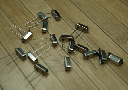
I bought a transmitter TM1000-1 and a receiver RM1SGS which both operate on a 433mhz Carrier. these units can be bought from ebay and are very cheap, I am also going to use the 16F648A microchip which Brad has used on alot of his projects and it comes with alot of program memory so we will never run out of program space for any project, I have also used a 16F876A but thats something we will talk about later.
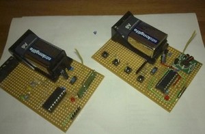
Then I built some prototype boards, one with a 16F648A microchip, transmitter and 4 buttons, and another with a 16F648A microchip, a receiver and 4 LED’s as you can see from the picture, you can also see the schematics as well.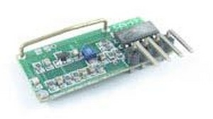

Prototype
Here are my original prototype boards. The Transmitter is the board on the right and the receiver is on the left.
Now that I had my two boards made up I started on the souce code for the transmitter, I sent out data from the transmitter and read the incoming data at the receiver with an oscilloscope, I found that the received data wasn’t always the same as the transmitted data.
I had a problem with the receiver picking up alot of random noise, so I found lots of information on the internet about Manchester Encoding, this type of coding was best suited for wireless transmissions but it ment that instead of only sending 8bits of data we had to send alot more data bits, manchester encoding works by transitions from HIGH to LOW (logic 0), or LOW to HIGH (logic 1), this also gave me other ideas, what if I wanted to use two receivers with one transmitter?
This lead me to more problems, so I came up with the idea of using a data packet system, this is where a number of different pieces of data are transmitted after each other in the form of a ‘packet’, this consists of a number of different sections I named them
(HEADER – ADDRESS – DATA – CHECKSUM)
Here is a breakdown of the four sections
- Header section – used to synchronise the beginning of the packet
- Address – this is a specific byte that the receiver checks, to make sure it’s intended for this receiver.
- Data – at least one byte of data.
- Checksum – a checksum byte, used to make sure that the data is received correctly, if it fails the data should be discarded.
So now I needed a way of checking the Packet data and checksum of the data so I used something called a Cyclic redundancy check (CRC), it is well known for checking fixed-length binary sequences in computer hard-drives, so I incorporated it into my project and wrote the source code for the receiver.
How it works
both boards are powered from a 9v battery which is stepped down to 5v using a regulator, when you turn on both of the wireless boards (transmitter & receiver) the power led will flash 3 times to indicate the board has power, when you then press any button on the transmitter board it will blink the power led and then send out the data packet to the receiver, obviously the address packet needs to be the same as the transmitter, and then turns on the corresponding led which has been programmed on the receiver board, this could have many functions like turn on a relay for an example? then when the same button is pressed again the corresponding led turns off. I also programmed the receiver code to flash the board power led when the signal is being received by the transmitter, and that is it for this part!
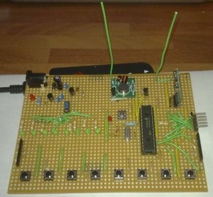
The Transceiver
I have integrated the souce codes above and decided to go a little further into this project and make a Transceiver. So for this part of the project I have used a 16F876A microcontroller mainly because it provides me with more I/O ports. I have used the same wireless modules however.
here is a picture of the transceiver prototype (notice the receiver to the top right of the board and the transmitter a little further to the left)
The idea of this project was to transmit and receive transmission packets of data by making two of these boards and then using it as a two way communication device, this board could be used for so many applications or projects or even using this transceiver project with a single receiver or transmitter board as described above, the choice is yours.
How it works
The board has both a 12v and a 5v voltage regulator, so it is recommended that you use a regulated voltage supply between 12 – 15volts, I wanted to use a 12v regulator as the TM1000-1 transmitter can actually handle up to 12volts – this will also increase the output range, so the power supplied to the transmitter is about 12v. The 5v regulator is to power the microcontroller and all the other parts on the board, including the receiver.
This project works in the same way as before in that when you power up the board the power led flashes 3 times and when you press a button on one board the corresponding led will light up on the other board etc.
The only difference is that the boards have 8 buttons and 8 leds and have a transmitter and receiver module on the same board, There is one other difference, I have used a mosfet transistor to turn the transmitter on when the data code is to be sent and then off when not in use, this stops generating a continuous carrier.
The other thing to note though is that the address on the transmitter on one board needs to be set differently to that of the receiver, in other words you setup one transmitter on one board with the same address as the receiver on the other and vise versa. this is to stop the receiver picking up your data packet that is being transmitted on the same board which results in all sorts of problems.
Some final notes
It is recommended that a 50ohm coax cable of 23cm is connected to the antennas of both the transmitter and receiver modules. This will increase your transmitting distance dramatically. If you use just standard wire then you will be subject to huge losses due to an impedance mismatch (which ultimately reduces your working distance).
The range I have got with these modules is at least 10 meters in open areas without any errors, but I am only using a piece of wire has the antenna on both the transmitter and receiver modules.
If you have any questions, feel free to ask in the forum.
You may freely use the information contained on this page for non-commercial applications. You may redistribute this information so long as you refer to the original author by name and also provide a link to brads projects site.