![[Brads Electronic Projects]](https://bradsprojects.com/wp-content/uploads/2017/06/BPLogo1-240x58.png)
Once installed, this mod will allow you to select from various modes all by pressing the reset button – you are presented with feedback by a multicolour power light (RGB LED).
When you first turn the console on you will be presented with a RED power light. This is telling you that you are running your system in 50Hz mode. If you press and hold the RESET button, the power light will turn off and then cycle through three colours – RED – GREEN – BLUE, it will repeat this cycle until you let go of the button.
- If you let go on RED you will select 50Hz mode
- If you let go on Green you will select 60Hz mode
- If you let go on Blue the SNES will reset – but will keep your last mode.
The Youtube video will give you a good idea of what’s going on.
Firstly, a little bit of background
When games were designed for the Super Nintendo console, they were designed to run at a screen refresh rate of 60hz. Which is the NTSC standard. So when games get ported over to enable them to be played on PAL consoles (which run at 50hz)
A couple of annoying things happen
- The games run slower
- The games no longer run in full screen
- You get the black bars above and below because PAL has more scanlines than NTSC. But by selecting 60Hz mode – effectively you can stretch the image to take up the full screen.

You may very well have seen that people have installed various switches to enable them to select between 50hz and 60hz modes.
But what if you don’t want to hack up your SNES? what if you don’t want ugly switches hanging out of your neat looking console?
We’ll that’s where this mod comes into it.
What you will need
- pic microcontroller (i used a 16f628a) but any pic with 6 I/O pins will do
- SNES mod hex file (to upload to the microcontroller) – download link at bottom of page.
- pic programmer
- RGB LED (common cathode)
- 3 x 150 to 470 ohm resistors (whichever you have, it really doesn’t matter too much)
- 1 x 10k resistor
- scalpel to cut a PCB track
- solder and soldering iron
- fine wire (i used the really thin enamel coated stuff – very handy for this sort of job)
- I also recommend having a solder sucker or solder wick to remove solder
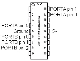
Here is the pic 16f628a / 16f648a microcontroller, with the pins that we will be concerned with.
You will need to construct a simple circuit on a piece of veroboard (or similar).
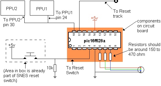
This circuit board will contain the pic microcontroller and the three resistors for the LED. Here is the complete circuit – the components on the board are outlined are contained within the orange rectangle.
Once the board is constructed, you need to cut a track that comes from the reset switch. You will then need to solder a wire to where the track was going to. In order to solder the wire into that small via (hole) you will need to scratch off the green coating with a sharp knife / scalpel.
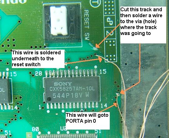
Once done, flip the circuit board over and you will see the underside side of the reset switch. You need to solder in your 10k resistor as shown and then solder another wire to the reset switch output and then put this wire through a hole to bring it to the top side of the board. ‘This is our output to the microcontroller’ goes to PORTA pin 5.
Now that those wires are done, we will move onto something a little more tricky.
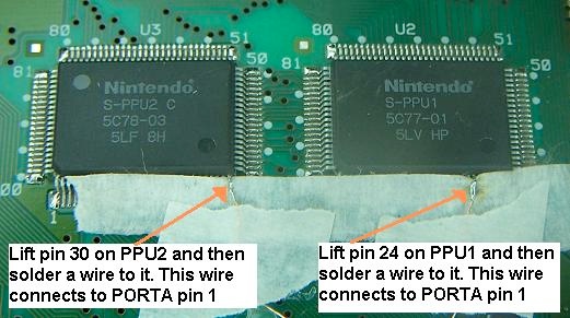
You need to lift to legs from the two PPU chips. You need to lift PPU1 pin 24 and also PPU2 pin 30 as shown. Once you have lifted them, place some masking tape underneath them to prevent them touching any other leg or pad. Then solder a wire to each of these legs. Both of these wires now go to the same microcontroller pin – which is PORTA pin 1.
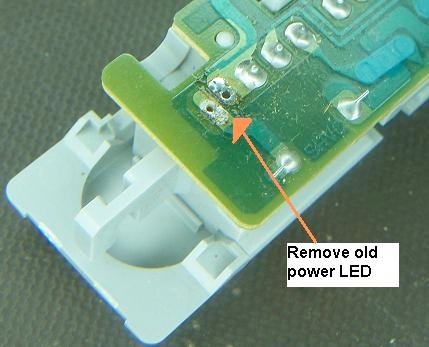
You will need to remove the old power LED. I use solder wick to desolder it and then pliers to pull it out. Here is the removed power LED.
You will also want to desolder and remove the resistor connected to the led .
Now you will have two pads in which to solder the new RGB LED to. solder the cathode of the RGB LED to the large pad (or the pad that does NOT goto the resistor) this pad is ground. Once done, solder one of the remaining three legs to the other pad (to keep the LED stable) just like this:
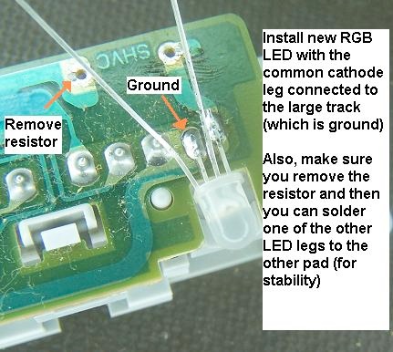
Then you can place some masking tape under the legs to prevent them shorting out.
Once done, solder on three wires to the Red, Green and Blue legs.
- RED connects to PORTB pin 0 (through the resistor)
- GREEN connects to PORTB pin 1 (through the resistor)
- BLUE connects to PORTB pin 2 (through the resistor)
Here is what the completed LED assembly should look like:

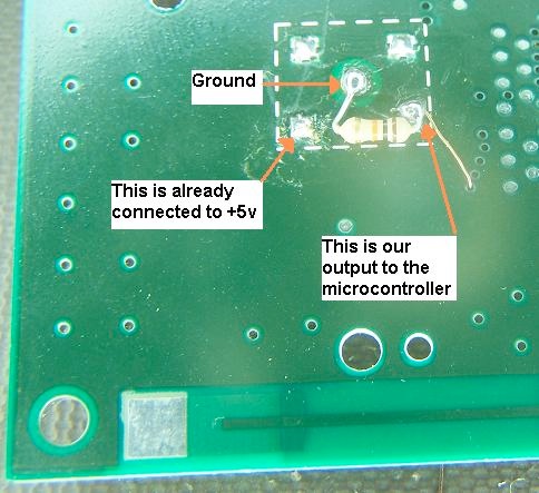
Finally, you need to connect power (+5v and ground) to the microcontroller. You can grab ground easily by soldering it to the big exposed solder plains on the board (the big silver rectangles around the edge of the board).
Then you can get +5v straight from the source by soldering it to the +5v output of the regulator:

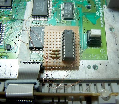
Now that all of your wires are in, you need to get back your circuit board and solder each wire to the relevant pin of the microcontroller. Your completed mod should look something similar to this:
Downloads