![[Brads Electronic Projects]](https://bradsprojects.com/wp-content/uploads/2017/06/BPLogo1-240x58.png)
Welcome to the page on generating video signals with your pic microcontroller. Before we get started I would like to pass on thanks and credit to Rickard Gunee. I learned about generating video from his tutorial page. I have just made this page to give you some info in my own words and also to give you some code examples and circuits that you can use to experiment with. I also recommend that you visit his site which can be found here

Generating simple composite video signals (for example a test bar pattern) is quite easy with a microcontroller. We will discuss a bit of theory behind video signals and then get into some instruction cycle counting to see if we can come up with a signal that will actually draw something on the screen!
A picture on your TV is made up of hundreds of ‘scan lines’ each line is drawn from left to right, once one line is drawn it will start drawing the next line down, again from left to right (just as if you were reading a book). There are a number of different TV standards from around the world – we will only be looking at PAL throughout this page.
PAL which stands for (Phase Alternating Line) requires 625 scanlines to create one image on the screen. An interesting thing about PAL images is that the picture is drawn one half at a time. I.E. The picture will start to draw from the very top line, and instead of then drawing the second line down, then third, then fourth etc… – it will draw the third and then the fifth, seventh, ninth etc… so it draws every odd line first. Then once it does a full screen of every odd line, it will then jump to the second line from the top and then ‘fill in the gaps’ The good thing about doing it this way is that even when we only have 50% of the image information, we can still basically see the whole image. But if we drew every line one after the other from top to bottom – after 50% is drawn – we don’t know what is on the bottom half of the screen because it hasn’t been drawn yet!
Now having said all of that, we can’t actually see all 625 lines on the screen. some lines are used for sync pulses and other things which we won’t really go into here. What we can see though is 576 lines on the screen. Now as we progress through the information on this page, you will learn that our microcontroller clock speed will deterimine how many pixels of resolution we can achieve in each scanline.
We will only be working with black and white images for now, because they are quite easy! (extremely easy when you compare them to colour…) Now the PAL standard works off varying voltage levels to determine what shade of grey we will get on the screen. Anywhere from black to white. black being 0.3 volts and white being 1.0 volt. So voltages inbetween these ranges are going to be your greys. How many greys you ask? Well lets say we managed to set it up so that we could change our signal voltage by 0.1 volt each time then this would give us 0.3 – 0.4 – 0.5 – 0.6 – 0.7 – 0.8 – 0.9 and 1 volt so that equals 8 different shades (including our black and white)
Well how about if we made our step size 0.05 volts? then we would double the amount of shades we could have (sixteen including black and white) or halve the step size again to 0.025 – now we get 32 shades and so on.
So back in the old days when we just had black and white TV’s, the way to draw the picture was one line at a time and the signal would vary in voltage between 0.3 volts and 1 volt to give us all the different shades that would make up the full picture. Here is one scanline of a PAL image.
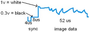
Looking at the image, We have 12us of synchronisation just before we draw any image on the screen itself. we then have 52us in which to draw one line of image data. so this is where our microcontroller clock speed comes into it. if we have a slow clock speed, for example that allows us to execute one instruction every 1us then we won’t be able to change our voltage level for our image data very quickly and therefor we end up with very poor horizontal resolution. The best we can hope to achieve in this instance is 52 pixels horizontal. you may not have a clue what i’m talking about at the moment, but I beleive it will all make sense one we start talking about the code and the super simple circuit that we will make.
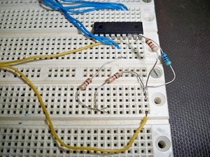
Okay so now having said all of that, let’s have a go at actually displaying some simple signals on our tv or monitor. We are going to use a simple two resistor voltage divider setup in this first example. I used a 470ohm resistor and a 1k ohm resistor. You would want one of them to be approx twice the resistance of the other. Connect one end of the 1k resistor to PORTB pin 0. Then connect one end of the 470ohm resistor to PORTB pin 1. Then you need to connect the two free ends of the resistors together – and thats basically the whole circuit! Your composite video output comes from the junction of the two resistors and of course, you will also need to connect composite video ground to ground of the microcontroller.
Here is what my setup looks like:

This super simple circuit will now allow us to experiment with displaying something on the screen. download the sourcecode and we will have a look at what is going on.
Download is located at the bottom of this page.
Now the first thing to mention with this piece of sourcecode is that we are operating the internal oscillator at 4MHz. This means that we are running at 1Mips (1 million instructions per second) and therfor this means that it takes 1us to execute one instruction.
This makes it a little easier for us to count clock cycles (remember that we have 64us for every ONE scanline – and 52us of that time is our visible image data)
So the first thing we need to do is send out our 4us sync pulse. This is contained within this piece of code:
clrf PORTB
nop
nop
movlw b'00000001'
the first 1us is contained in the clrf PORTB instruction. so we are sending ZERO volts through to the screen. we then have two NOP statements which holds the ZERO volts there for a further TWO microseconds. the last instruction serves two purposes. it gets us ready for the next 8us pulse by storing b’00000001′ into the w register. it also takes 1us to perform this instruction so it also acts as our last 1us delay in the total of 4us in the sync pulse.
Now our first 4us is up, we then move onto holding b’00000001′ on PORTB for 8us
movwf PORTB
nop
nop
nop
nop
nop
nop
movlw b'00000010'
The first instruction copies what was in the w register (b’00000001′) into PORTB. this instruction takes 1us. then we have a set of 6 nops which delay for an extra 6us. So now we have taken 7us to do all this. We just need to hold it for one more microsecond. We do this with the final instruction which is movlw b’00000010′ this serves two purposes it gets us ready to send a voltage greater than 0.3volts to the screen. (which means that we will actually be able to see something in the next piece of code) this line of code also takes 1us so it acts as the last 1us in the 8us delay.
Now that we have finished the sync pulses, the next 52us is our visible data. so whatever we put on PORTB from now on, will be displayed on the screen. The remainder of the code is dedicated to sending out different combinations of 1’s and 0’s to PORTB (namely to pins 0 and 1) this has the effect of varying the voltage going to the screen by use of the voltage divider resistor network.
We can have one of four combinations at any one time. these being 00, 01, 10 or 11. 00 and 01 will give us black on the screen, whereas anything above 01 will give us a voltage great enough to display a shade of grey. So we first send 10 which is a dark grey, we hold it there for a while then we change it to 11 which is white. we hold it there for a while and then go back to 10. we hold it there for a while and then finally we send out 01 which is black.
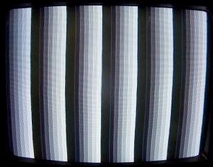
So the actual image we get on the screen is this:
You can see in the picture that we have dark grey, then white, then dark grey then black. It is important to remember that everytime we run through a complete cycle of the begin routine we are only drawing ONE scanline, the reason that this screen is filled with bars is because we are repeating the same loop of code over and over again. so we just keep drawing the same line over and over and over etc…
Have a think about this…
Since we can only execute one instruction every 1us and we only have 52us in which to draw one scanline – can you see that at maximum we can have 52 individual dots per scanline? if we wanted a greater horizontal resolution we would need to increase our clock speed. Or what if we wanted more combinations of grey scales?
Well in that case we can add an extra resistor twice as big as the previous (in my case, it will be a 2k resistor) so now we have a resistor network with three resistors 470 ohm – 1k ohm – 2k ohm.
Lets have a look at the new circuit.
You will need to disconnect the 470 ohm from PORTB pin 1 and put it in pin 2, then disconnect the 1k resistor from PORTB pin 0 and put it in pin 1. Then finally you will put your new 2k resistor in PORTB pin 0 with the other end connected to the same junction as the 470 ohm resistor and the 1k resistor. mine looks like this
Note – i have used two 1k resistors in series to create the 2k resistor.
In this next source code example all we are doing is incrementing PORTB every 1us, this gives us the effect of increasing the greyscale brightness through the various combinations. The brightest will be when we send ‘00000111’ to PORTB, this means that all three resistors will have a logic 1 on them.
You can download the source code at the bottom of this page.
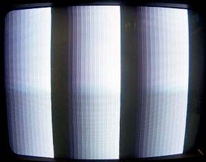
Here is what the new signal will look like:
Notice how now we have more shades of grey? this is due to the extra resistor. and also notice how wide the bars are? this is because the microcontroller is running quite slow and it takes 1us for PORTB to increment by one. if we doubled the speed of the microcontroller, we could make these bars half the size (or to say it another way, we could fir twice as many bars on the screen)
And now what if we add another resistor to the network? I.E one that is twice the previous – 4k ohm.
Here is what it looks like if we added this resistor and ran the same sourcecode as the last.
Now we have more shades of grey but still the same horizontal resolution.
I know this run through is quite simplistic but it gives you a basic insight into how we can construct a simple circuit and display something on the screen.
This is something i certainly want to look into further I.E. I want to be able to display graphics and even make simple games by this method – but I have much to learn. I will be sure to let you all know more as soon as I learn more.
I hope this page was helpful nonetheless.


Great article dude, I might even take this a step further and try using the Pics internal D/A. Cheers bro
This was useful for me to do first steps in creating videosignal for 8051 based microcontroller.
Thanks.
thank my friend
how to do this without a microcontroller.
only with ttl chips