![[Brads Electronic Projects]](https://bradsprojects.com/wp-content/uploads/2017/06/BPLogo1-240x58.png)
The great race is a very addictive and easy to build little game. It is made from readily available and inexpensive components and was actually the first game I designed with a microcontroller.
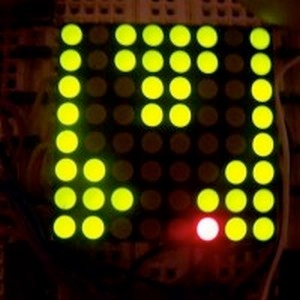
The idea of the game is to drive your car (the red dot) to the left and right of screen to avoid the oncoming obsticles. There are eight levels of play and as you increase in level, the speed of the game also increases. If you crash your car, the screen will blank and then display the level number that you made it up to – then you press any button to reset the game. If you manage to make it all the way to the last level, you will be presented with a smiley face to let you know that you have finished the game. You then press any button to reset the game.
Please note this video clip is of the game before it was completed.
About the circuit
The circuit consists of just to chips, two push buttons, 11 resistors and one 8×8 bi-colour display. All these components can be bought for under $10. How it works: The 8×8 bi-colour display is multiplexed i.e all the anodes are connected together in rows- 8 rows of led anodes, then all the red cathodes are connected together in columns – 8 columns of red led cathodes, and finally, all the green cathodes are connected together in columns – 8 columns of green led cathodes. So all up we have 8+8+8 = 24 pins for our 8×8 led display.
Since it is multiplexed, we cannot just turn on all columns at one time in order to draw a picture – we need to activate each column of led cathodes one column at a time, and then grab 8 bits of data from the microcontroller to be displayed in that column. We hold that data on for a split second, then we activate the next column in sequence – grab 8 bits of data and then hold that info on the screen for a split second.
We do this until all 8 columns have been activated and displayed their data, if we do this fast enough the screen will appear to give us a steady image! (sort of like how your television works…) This is where the 7442 comes in handy, we input a 3-bit number (from 000 to 111) to activate just one column of led cathodes at any one time, so the first column will be activated at 000, then the second at 001 – then all the way upto the last column at 111. NOTE: I could have used a 1 0f 8 decoder instead ( i think they are 74138) but i just didn’t have any, thats why i used the 7442)
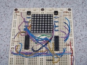
The Prototype
Here is a photo of my original prototype using breadboard. How handy is breadboard!
Driving around

About to Crash
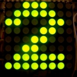
Crashed on Level 2
If you finish the game, you get a smiley face.

Parts list
- 1x pic16f648a microcontroller
- 1x 8×8 bi-colour led display
- 1x 7442 1 of 10 decoder (or you could use a 74138)
- 8x 100 ohm resistors
- 3x 10k ohm resistors 2x mini push buttons
You can download the source code and schematic here:


And can the 16f628a also be used, are they compatible with all your projects?
Thanks, Kieran
The 16f628a is the microcontroller that I used with my older projects, these days I use different 18f pics (like 18f4550 or 18f26k22) and also Arduino’s
If I lower the resistance of the 100 ohms they should be brighter?
Sorry for the late reply Kieran, if you reduce the resistance to 100 ohms they will certainly be brighter 🙂
Hi Kieran, The 74138, 74LS138, 74HC138 etc… are all going to perform the same function. The letters in between the numbers tell you details such as if it is a lower power chip, high speed chip etc…
So you can use a 74ls138 but I would recommend a 74HC138 because the ls version will cause the LED’s to be a little dimmer than the hc version.
Hi, I was wandering if the 74138 chip in the Great Race project is the same as 74ls138 from this website?
http://www.taydaelectronics.com/74ls138-74138-decoder-demultiplexer-ic.html
Thanks
Hi, I was wandering if the 74138 chip is the same as 74ls138 from this website?
http://www.taydaelectronics.com/74ls138-74138-decoder-demultiplexer-ic.html
Thanks