Now that you have mastered making one LED flash, lets move onto using 8 LED’s.
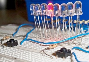
If you have ever seen the TV series Knightrider then you will already know what this circuit will do. Basically we have 8 LED’s connected to PORTB. We will program it in such a way so that each LED will turn on, one at a time from left to right and then go back again.

What you can expect to learn in this tutorial
- Explanation of the RRF instruction
- Explanation of the RLF instruction
- Explanation of the carry bit within the STATUS register
- How to make your code more efficient
- how to use loops
What you will need
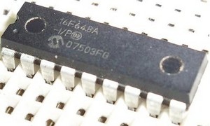
- Pic16f628a or pic16f648a microcontroller
- Programmer
- Electronics breadboard
- 8x LED’s (any LED’s will do)
- 8x resistors (any value between 150 ohms and 1kohm will do)
- Hookup wire
Build it
First things first – You will want to build the circuit.
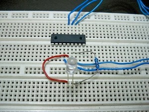
If you recall from our last circuit (the LED flasher) we connected one LED through a resistor to PORTB pin 0 – and then the other side of the LED to ground. This allowed us to set (bsf) and clear (bcf) PORTB pin 0 in order to get the LED to flash.
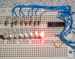
Now we are going to build on that circuit by connecting seven more LED’s and resistor’s to the seven remaining pins on PORTB – I.E. connect a resistor to each of the remaining PORTB pins, then to the anode’s of the seven LED’s, then the cathodes will all connect to ground.
Your circuit should look something similar to this:

Code it
Once you have your circuit built, it is time to get into the code.
We will be looking at a number of different ways of achieving our task. The first three sourcecode examples are quite inefficient. We then look at a fourth piece of sourcecode which is very much improved but it still achieves the exact same result. You should be able to see by the end of this tutorial that there are numerous ways of achieving programming goals and as such, there is always the possibility of improving on your code.
You can download all four versions of source code at the bottom of this page.
This first example is quite easy to follow.
All we are doing is initially clearing every pin on PORTB. This means that as soon as we start running this program, that all LED’s will be in the OFF state. From here it starts to look just like it did in our LED FLASHER program. We set PORTB pin 0, thus turning on the first LED.
Then we call the delay as usual to hold that first LED ON just for a moment, then we turn it off. Straight after turning it off – without any delay, we turn the next LED ON and hold it on for a moment by calling the delay. Then we turn it OFF and immediately turn the next successive LED ON – and so on and so on.
Once it gets to the last LED, it simply starts coming back the other way (towards our first LED. once it has come all the way back to our second LED, the program loops back to the beginning of the sourcecode and does it all again over and over untill we remove power.
As you may be able to see, we need quite a few lines of code (and therefor quite a bit of program memory) in order to perform this little task. How can we make it better? We will work towards making our code more efficient – but first let’s have a quick look at a different way of achieving the same result.
(Open up the second piece of sourcecode in the download at the bottom of this page)
Having a look at the sourcecode, you can see that we have now done away with individually setting a certain bit, holding that bit on with the delay, then clearing that bit. Now we are sending a full BYTE of data to PORTB every time we want the led to move one space. This is achieved by use of the MOVLW and MOVWF instructions. By using binary digits (denoted by the b’ ‘ ) it is really easy to see what LED’s will be ON and what LED’s will be OFF. for example – if we wrote b’00000001’ we can immediately see that all LED’s will be OFF except for the right most LED which will be on. That’s what is so great about using binary!
Alternatively we could use HEX digits, DEC digits or even OCT digits – you won’t save any program memory space, but some people prefer to use these number systems rather than BIN (binary). As a side project – why don’t you have a go at making this LED SCANNER do the same job by using decimal digits instead of binary, or maybe even hexadecimal? It’s quite easy, you just need to change the letter infront of the digits and then change the binary to the equivalent number for your chosen number system.
• h is for hexadecimal
• d is for decimal
• o is for octal
• b is for binary
For example, if we were to send the binary number 00000001 to PORTB it would be exactly the same as sending HEX 01, DEC 001 or OCT 001. They are all the same number. Or if we sent the binary number 00010110 it would be the same as sending HEX 16, DEC 022 or OCT 026. I guess you could liken it to a nick name. Your name might be ANDREW and you might have the nickname ANDY. So it doesn’t matter if someone said ANDREW or ANDY – they are still referring to you.
So you should be able to see in this example, that we first clear PORTB so that all LED’s are off when we first turn the circuit on. Then we send eight bits of data to PORTB which turns the right most LED ON – we then call the delay to hold PORTB in this present state. Then the very next instruction sends a brand new 8-bits to PORTB whereas the in previous sourcecode example, we were just concerned with one bit at a time. It still achieves the same result, but is a good learning tool to show you how we are able to use different instructions to achieve the same goal.
Now, just before we get to the nice an efficient version which will use loops, we will have a look at a couple of new instructions – these being rlf and rrf
(Open up the third piece of source code from the download at the bottom of this page.)
rlf PORTB, f
rlf means rotate (or shift) the data stored in whatever register or PORT that we say through carry and store the answer back in our register or PORT or store the answer in our w (working) register. So in our case we are shifting all the data in PORTB one space to the left, the left most bit will be shifted into the carry flag of our status register and whatever was in the carry flag will be shifted into the right most bit of PORTB the ,f at the end of this instruction means ‘store the answer back in PORTB’. The other option would be to change the ,f to ,w and that would mean ‘store the answer in the w register instead of PORTB.
Here is an animation that i made up to show you how the rlf instruction works:

As you can see, we have started out with 00000001 stored in PORTB (just like in the source code) Also, the carry flag is initially cleared (so it contains a zero) everytime we do the instruction rlf PORTB, f we are rotating (or shifting) the data in PORTB one space to the left, each bit goes through the carry flag BEFORE it rotates back to the biggening (the right most bit) Can you see why we initially clear the carry flag before we start rotating left? i.e we use the bcf STATUS, C instruction to clear it?
Well, the answer is because if we did NOT clear it, it may have been set for some reason (it could possibly have been set by a previous instruction) and therefor when we start to rotate our data, we would have two LED’s on instead of just one (because the logic 1 that was in the carry flag would have been rotated into PORTB. so we don’t want the chance of that extra LED being there so to be sure of what will happen, we simply clear it.
Why don’t you try chaning the instruction bcf STATUS, C to bsf STATUS, C you will find that after the very first rlf instruction, that you will have two leds shifting around the place.
You may also notice that by continually using rlf instructions, the LED does NOT start to come back the other way, but it just goes back to the start. In our code, we prevent the logic one from ever going past the left most bit. as soon as it gets to the left most bit, we start using the rrf instruction to make it go back the other way.
This is what our code is actually doing – notice that the logic 1 NEVER gets into the carry flag?

rrf PORTB, f
This instruction is practically the same as the rlf instruction, except it causes our data to go the other way. So this time, the right most bit will shift into the carry flag and then shift back into PORTB at the very left most bit.
Okay, now let’s get onto the final version of the knightrider sourcecode. This final version uses loops (like we looked at in tutorial 2) to keep our code size down and thus saving program memory space.
If you look back at the third code version, you can see that we are basicially doing two things over and over again (shifting left a few times, then shifting right a few times and then doing it all again!) Well how about we just use one rlf instruction and one rrf instruction but set it up so that it does each one a certain number of times before moving onto the next piece of code?
That’s exactly what we do in this fourth version of the code. We declare a brand new variable named direction. we then proceed to load up this variable with the decimal number seven d’07’ so have a think about it. We start with the right most LED turned on. how many times do we need it to shift left before it will light up the left most LED? SEVEN!
So lets check out this piece of code:
shift_left
rlf PORTB, f
call delay
decfsz direction, f
goto shift_left
movlw d'07'
movwf direction
(Open up the final version of the source code in the download at the bottom of this page.)
Basically, we shift our LED left one space, then we call the delay to hold this LED on for just a moment. then we decrement our direction variable by one and then we check to see if the answer is zero or not. if it NOT zero, then we jump back to the shift_left label and do all of that again. But when the answe IS zero, we set our direction variable back to SEVEN, ready to shift the LED right seven spaces.
Maybe you could try and change the value that is loaded into direction? change it to decimal 5, or 4 or perhaps 3? (make sure you change it in every instance that we load direction with a value (we do this three times throughout our code)
Well, I think that is just about it for this tutorial. It is certainly the most indepth so far and I hope that you learned alot from it.
If there are any questions or concerns – feel free to leave a comment.
![[Brads Electronic Projects]](https://bradsprojects.com/wp-content/uploads/2017/06/BPLogo1-240x58.png)


Brad, I am a beginner. Thanks for what you have done on here, I am learning a lot from here, when I couldn’t get any good information from anywhere else. Yours is very easy to understand
Hi Seth, I am glad it’s been helpful for you. I would like to make it a bit easier by including circuit diagrams but I am just very short of time at the moment. Let me know if you need any help with the tutorials though.
Net got so many search results and I’ve find it very resourceful to me for being a starter. Nice, goodluck and more power.
Great to hear that you are enjoying the tutorials Greg!
The PICKIT 3 supports the PIC16f628A and 648A so you shouldn’t have any problems using that with these tutorials.
One day I’d like to get around to making other tutorials (maybe in basic or arduino). I just need to find some time…
I’ll be looking forward to them. Thanks again Brad.
Greg
Really enjoying these tutorials Brad, thanks very much for taking the time and effort to make them for us.
I’ve been fascinated by the idea of programming PIC’s for many years but always ended up confused and despondent with previous efforts. Your tutorials so far have made things easy to understand, and the code downloads are the icing on the cake. I’ve just ordered a Pickit 3 (i’m assuming it’ll be similar enough to the pickit 2 that it won’t be a source of confusion!) and a 16F628A so I’ll be flashing some LED’s soon hopefully!!
Thanks again mate,
Greg
Great to hear you like the tutorial! God Bless 🙂
VERY NICE. MAY ALLAH REWARD YOU.