Seven segment displays are extremely useful devices. We can quite easily drive one, two, three or more seven segment displays with just one microcontroller – we will start with just one so you can see how the circuit and code works, then we will build on that to get to four seven segment displays running from one 16f648a microcontroller.
What you can expect to learn in this tutorial
- how to connect one seven segment display to the microcontroller
- how to connect two seven segment displays to the microcontroller using transistors
- A quick introduction to the retlw instruction
What you will need
- pic16f628a or pic16f648a microcontroller
- programmer
- electronics breadboard
- 2x common anode seven segment displays
- 2x NPN small signal transistors (i use pn2222a)
- 9x resistors (any resistor between 100 ohms to 1kohm will do)
- hookup wire
If you have never worked with seven segment displays, they really are quite simple. Internally there are seven LED’s arranged in a figure eight pattern. depending on which segments (or LED’s) within the display that we turn on, will depend on what number or character is on the screen. You can purchase these displays in two different varieties – either common cathode or common anode.
This tutorial we will be using the common anode seven segment displays, this simply means that all the LED’s anodes are connected to a common point. Then in order to turn on each LED, we simply connect ground to the corresponding pin. Lets have a quick look inside a common anode display:
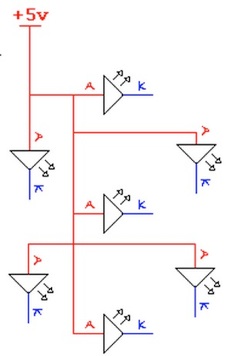
Here you can see that there are seven individual LED’s. Internally all the anodes are connected together and all cathodes are separate. If we connect +5v to the common anode connection, we can now turn on any segment we like, just by connecting ground to one of the seven cathodes (making sure to use a resistor of course!)
This image shows the pinout for these displays:

Notice how there are two common anode connections? you don’t need to connect both of them, either one will do. This just makes it handy for if you were designing a complex circuit board and it might be hard to get a connection to the top common anode, you could alternatively use the bottom common anode etc… so for our exercises, just use which ever one you want. Also note the dot in the picture. If you were designing something like a calculator, you would use the dot as the decimal place. We won’t be using it here though.
Now before we build the circuit, have a think about this,
If you wanted to display the number five on the screen what would you do? what would you connect and where?
Well the answer is, you would connect +5v to the common anode, then ground (through resistors) to a, f, g, c and d just like this:
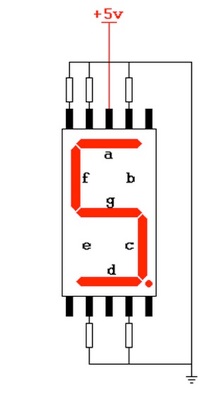
Now it is time to build our first circuit:
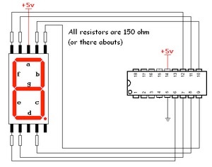
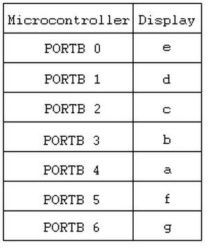
This table will help with connecting up your seven segment display to the microcontroller.
Once built, your circuit should look something similar to this:
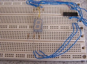
You can download all source code files via the link at the bottom of this page.
Now if you open up the first source code file you will notice that this program will simply count from ‘0’ to ‘9’ and then repeat again in an infinite loop. Also notice that in order to display each number, we need to send a certain combination of 8-bits to PORTB.|
So having said all that – do you know why a logic zero will turn on an LED? Well the answer is simple. Remember that the seven segment displays are common anode – all the anodes are connected to +5v already, so in order to turn an LED on, we need to connect the cathode to ground (through a resistor) what logic is equal to ground? LOGIC ZERO OF COURSE!
Some things to experiment with in this sourcecode
Try and count through all the hexadecimal digits I.E 0, 1, 2, 3, 4, 5, 6, 7, 8, 9, A, B, C, D, E and F.
What combination of 1’s and 0’s do you need to make the extra digits?
Alright, now that we know how to make the different digits, now we can move onto adding more displays.
Modify your circuit to match this one below:
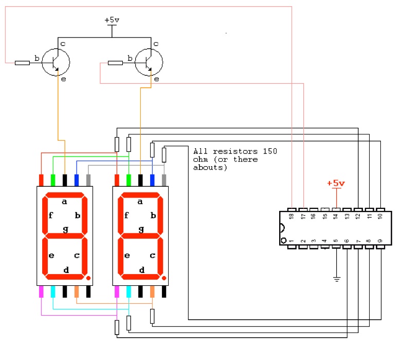
Here is what the revised circuit looks like:
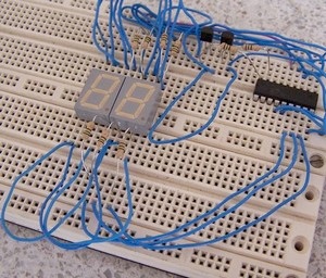
If you run the second piece of code from the download on your circuit you should be presented with the number ‘0’ on one display and the number ‘7’ on the other, but you only see one number at any one time (thats because we alternate between the two displays.)
You will notice that we control the first display through the transistor to PORTA pin 0. By sending a logic ‘1’ to PORTA pin 0 we are turning the transistor ON if we are turning it on then we have now effectively connected +5v to the common anode pin of the first display.
If we send a logic ‘0’ to PORTA pin 0 then we are turning the transistor OFF and therefor disconnecting +5v from the common anode pin of the display.
Likewise, the second display is controlled by sending a ‘1’ or a ‘0’ to PORTA pin 1. So the key thing to remember is:
PORTA pin 0 drives the first display
PORTA pin 1 drives the second display
Now you may ask “well what is the point if we can only see one number at a time?” I’m glad you asked, you can answer your own question by reducing the delay time. What happens when you reduce the delay from 255 to 100? or 50 or even lower?
At what number does the display stop flickering?
So there’s your answer, even though we can only have one display on at anyone time, we speed up the rate at which they are turned on and to the human eye, it looks like one steady display!
Can you think of something useful to do with a display like this? some sort of counter?
Well before i leave you, i thought i’d do one last piece of source code which is just a bit of fun (well I think so) basically this source code is going to make your display do this:

Maybe not the most exciting thing you have ever seen but it gives you a little insight as to how we can use data look-up tables to store information ready to be read and then written to our display. you may also notice that in order to achieve the above animation, we are going to need to switch between the left and right displays being activated.
I am not going to go into this piece of sourcecode in any detail because we will be dealing with look-up tables in a later module. But if you had a look at the code all we are doing is calling the table and as such, we increment the program counter by one more everytime we call it. this means that everytime we visit the lookup table, we grab the next retlw instruction – so what is a retlw instruction?
The retlw instruction is basically this – return to where we came from BUT also store this byte of information in the w register when we go back. So really it acts just like the return instruction but it stores a byte of data in W as we return.
As stated before, we will talk more about these instructions in a later module, but i thought i would throw it in here as an introduction.
Well that is all for this module, thanks for looking and God bless.
Downloads
![[Brads Electronic Projects]](https://bradsprojects.com/wp-content/uploads/2017/06/BPLogo1-240x58.png)
very good blog, very useful for the information and the structure of the writing style, I will come back again for more information
Where I could find the materials?
Where I could buy the materials?
Hello, I have built the key pad and 1×7 segment display using the same code with some modifications for a 16f690. Everything works well. I understand well The diagram for adding the second 1×7 segment display. But I am trying to create a code that may work with the 2 displays. It has not been easy since I have not found the way how to enter, fr example the number 25 from the key pad. I know you have given a code where you put a number with 2 digits but the code does not grab the number from the… Read more »
Hi Christian, unfortunately I a will be of little help to you here. I have not programmed anything in assembly language for nearly 10 years, I have mostly been using Basic and C for all my projects since about 2009. It does get quite tricky to implement what you are asking – but essentially you need some variables which can store the digits that you read from the keypad – you then need to send these variables to each display. You also need to cycle between these two displays – with each display showing its associated variable. Of course, you… Read more »
Thanks Brad, yes I thought abut the variables. I just need to know how to get the variable since, for example, if I try to write number 23, first, number 2 has to be passed to the variable but then how to send the second number to a second variable?, I mean, I need to differentate that the second number that I Key in the key pad Will be placed in the second variable and not in the first one. It is like a valve that always moves between first variable and second variable (back and forth) but the number… Read more »
Yes you are right, you do not to differentiate one variable from another. I won’t be able to give you any code (because it’s been many years since I have worked in assembly). But you could have another variable which tells you how many times a key has been pressed. This way you have a reference point for where to store the first and second number that has been pressed on the keypad. When a key is pressed, you would store that number, increment the variable that stores the number of times a key has been pressed and then have… Read more »
You have the ability to explain things very clearly! Thank you very much!
I want to control the output of 7segment display by two switches, one to increase and one to decrease. how do I do that. please help
Good Evening. I have built your Tutorial 5 circuit with 2 each seven segment displays, common anode. When I try to compile the version 3 code I get a warning error” can not open Include file 16F628A.inc.
I changed from 16f648a to 16f628a as suggested.
I am also using PBP3 Microcode Studio. Is your code compatible? I thought it would be. Can you steer me in the right direction as to the problem? Thank You for your help and support.
Thanks Again
Tom
I did find in the code where it is mentioned to select the 16F628A and that changes the config information.
Thank You Again,
Tom
Great project! I am new to this website but hope to get more into it. However, I am not familiar with this language. I only know Pic Basic Pro and PBP3. I am most familiar with the 16F628A and use it in virtually all my circuits.
I, like comment #12, Nov. 6, 2016 at 2:57 am, would like to see the assembly code for 16F628A if possible.
Thank You,
Tom
How to make PLC circuit with assambly Code using pic 16F628A
yes Brad
Hi Victor, unfortunately I have not used assembly language in many years now and have moved on to other programming languages for my projects. Were you looking for assembly tutorials specifically?
How can l implement it on PIC18F4520
please help me by source code for assembly level language that display large size string in seven segment electronics.
I would like to thanks you more please help me
please help me by writing assembly level language that display large size string in seven segment electronics.
Hi,
Very nice tutorials very good for beginners like me.
How can I impliment it in PIC18F452
7segment interfacing with pic 16f877a circuit diagram and discription,and i want source code for pic 16f877a.