Unfortunately this project did not work out as well as I had planned. I could not get it to do animations. It would happily display one individual frame but when I wanted it to scroll through a number of frames, I ran into all sorts of problems.
Having said that, I did come up with a semi-working display that could show static pictures. So have a read through and hopefully you will find something of interest.
Please note that I have not documented this project because it was never completed to a fully working condition.
The circuit design was very similar to my original 8×85 RGB POV except I just had to add some extra video ram to account for the extra LED’s and a larger microcontroller to handle the extra control lines.
The project was broken up into five separate boards.
This board contains the PIC18f4550 Microcontroller and the 64Kb EEPROM.
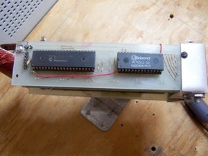
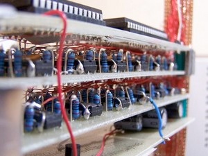
These two boards in the middle contain twelve 74373 chips which hold onto the display data before sending them to the LED’s.
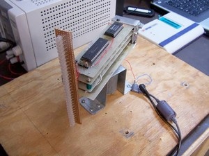
This image shows the complete unit mounted on the motor, inparticular you can see the 32 RGB LED’s mounted vertically.
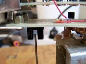
This photo shows the sensor circuitry and the nail that passes through the sensor to tell it when to start drawing each frame.
Here you can see the underside of the power / sensor board. I transferred power to the board using the motor shaft as the ground connection and then a graphite brush and metal casing to transfer the +ve end of the power supply to the spinning board.
This method worked okay although I have since come up with a better method of transferring power to the board and you can see this in the new and improved one chip pov project.

Parts List
- PIC18f4550 microcontroller
- 32 x RGB LED’s (common cathode)
- 12 x 74373 chips
- 96 x 150 ohm Resistors
- 27512 EEPROM
- 12Volt motor
- Please see the 8×85 RGB POV for the sensor circuit
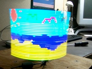
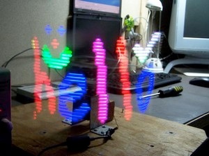
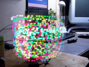
Here are a few photo’s from some of the pictures I drew for the display.
![[Brads Electronic Projects]](https://bradsprojects.com/wp-content/uploads/2017/06/BPLogo1-240x58.png)
