We’ll so far we have been using the microcontroller to make some nice LED’s flash and do pretty things. But what about using a couple of pins as inputs? That’s exactly what we will be covering in this module.
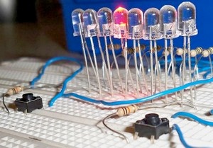
This circuit has a left push-button and a right push-button. You press the left button to make the LED shift left, and the right button to shift it right. The code is designed so that when the LED reaches the extreme left or right. It prevents us from going any further in that direction and will only allow us to go back the other way. This module is quite interesting so read on!
The good thing is, you can keep your previous knightrider scanner circuit and you just need to add four components to it. They are:
- Two mini push-buttons
- Two 10k ohm resistors
So if you have not got the scanner project from module 3 built yet – go back to that module, build the circuit and then return here.
What you can expect to learn in this tutorial:
- Explanation of the btfss instruction
- Explanation of the btfsc instruction
- Continuation on working with sub-routines
- How to set ‘conditions’ in your project
- How to set your I/O ports as inputs
What you will need:
- Everything from the previous tutorial
- Two push buttons
- Two Resistors (1k to 10k will do just fine)
In digital electronics we need to be absolutely sure about what logic level is at an input. so we can’t simply have a switch that has a common connection and then +5v on one side and ground on the other. This is because when we want to switch from one to the other E.G. from ground to +5v, we have an ‘in-between’ region of the switch where our common connection is not connected anywhere I.E it is not connected to +5v OR ground, this poses a problem to digital electronics because we could get unwanted results.
Having said that, we can fix this small problem by using a cheap 10k ohm resistor. Connect your two push buttons like this:

You can see here that as far as the input to the microcontroller is concernced, it only ever receives one of two possible states. These being a logic 0 or a logic 1 – THERE IS NO IN-BETWEEN STATE. This is all thanks to the resistor.
When the switch is not pressed (open circuit) our micrcontroller has a direct connection to ground through the resistor – therefor we get a logic 0. When we push the button (short circuit) we have now created a current path from ground, through the resistor to our power supply +5v this means that the resistor is dropping +5v and since we are connected to the +ve side of the resistor, we will be receiving a logic 1 (+5v)
You don’t have to use a 10k resistor, I use them because i have lots of them, and it’s a good value to use because it limits the current by quite alot and we really aren’t concerned with current here, just if there is 0v or +5v.
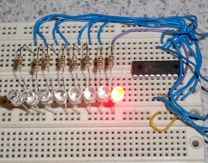
So, i’m guessing that you haven’t pulled apart the knightrider scanner circuit – so grab it again and add two of these push-button circuits.
Connect +5v to one side of the button, then the other side of the button goes to microcontroller PORTA pin, 0. The otherside also goes through a 10k resistor to ground.
And now do exactly the same thing except this time, connect your output to PORTA pin, 1. We will be using PORTA pin 0 and pin 1 as inputs. PORTA pin, 0 will control making the LED’s move left and PORTA pin, 1 will control making the LED’s move right.
Okay, now that your circuit is built – it should look something just like this.
Notice that the left button is connected to PORTA pin, 0 and the right button is connected to PORTA pin, 1
Now is a good time to remind you that if you are unsure of how to build this circuit up to this stage, you will want to go back to module 2 to learn how to connect one led, then goto module 3 to learn how to add the remaining seven LED’s and then you get to this module, to learn how to add your button to the circuit.
And now the circuit is built, we can get into the sourcecode which you can download at the bottom of this page.
The first thing to look at in this source code is that we have changed our PORTS. To be more specific, we have made pins 0 and 1 on PORTA both inputs. we did this by changing the value that we send to the TRISA register.
This is the piece of code that we were using:
bsf STATUS, RP0
movlw b'00000000'
movwf TRISB
movlw b'00100000'
movwf TRISA
bcf STATUS, RP0
Notice in the above code, that we have made PORTB all outputs by sending all zero’s to the TRISB register? Also, we are making pin 5 on PORTA an input. (we’ll actually it can only ever be an input – you can’t make pin 5 on PORTA an output.) We now want pins 0 and 1 on PORTA to be inputs – This is very simple – we just need to change them from zeros (which means OUTPUT) to ones (which means INPUT) Like this:
bsf STATUS, RP0
movlw b'00000000'
movwf TRISB
movlw b'00100011'
movwf TRISA
bcf STATUS, RP0
The changed line of code is in red above. Remember that the least significant bit is to the right. so now starting at the right we have pins 0 and 1 as inputs, then pins 2, 3 and 4 as outputs, then pin 5 as an input and finally, pins 6 and 7 as outputs. PORTB remains unchanged with all pins remaining as outputs.
It’s very handy that we can individually make a certain pin an input or an output rather than having to set a whole port as input or output.
Okay, the next thing to look at is our main routine.
We have a main routine with the heading begin just like in our other examples. You will find in the main routine that we don’t do anything but call a couple of sub-routines and that’s it! This can be very handy when programming because you can piece your program together in chunks that fit in their own relevent space.
The first sub-routine we call is check_left, here is the code:
check_left
 btfsc PORTB, 7
 return
 btfss PORTA, 0
 return
 rlf PORTB, f
 call delay
 return
The first two lines in this sub-routine are there to prevent us moving the LED any further left IF the left most LED is turned ON. to do this, we use the btfsc instruction.
The btfsc instruction means ‘have a look at whatever bit i say, within whatever register or port that i say. If the digit in there is a ZERO then skip the next line but if the digit in there is a ONE, then continue on with the very next line.’
So as you can see, this is quite an in-depth instruction. In our case, we want to check to see if the left most LED is turned on (PORTB pin 7) if it is turned on then it will do the very next line, which is a return instruction so we never get to move left again one space if this left most LED is on. BUT if the LED is not turned on (so PORTB pin 7 IS a ZERO) then we skip the next line (I.E. we skip the return instruction) and we go on with the next piece of code which is where we check if the button has been pressed.
Now this is where the btfss instruction comes into it. btfss means exactly the same thing as btfsc EXCEPT if the answer is ONE it will now skip the next line, but if the answer is ZERO it will go on with the very next line.
So, if we managed to get to this point (I.E. the left most led was not turned on) then we now check to see if the push-button has been pressed. If it has NOT been pressed, we will have a logic ZERO at PORTA pin, 0. This means that we will go on with the very next line – in this case the very next line is a return instruction, so we don’t move the LED at all. BUT if we had pressed the button, this means that we would have a logic ONE at the input of PORTA pin, 0 and this means SKIP the next line and go on with the code from there.
Then all we do is a simple rlf instruction to move the data in PORTB left one space. We then call the delay to slow things down a bit – and finally, we return back to our main routine.
The next line in our main routine is to call the check_right routine. This is very VERY similar to the check_left routine. Let’s have a look:
check_right
 btfsc PORTB, 0
 return
 btfss PORTA, 1
 return
 rrf PORTB, f
 call delay
 return
You can see here that we are checking if the rightmost LED is turned on by checking PORTB pin, 0 (btfsc PORTB, 0) Remember, we do this to prevent us from moving the LED any further right when we are already at the extreme right. If if is not at the extreme right, it will allow us to continue on by skipping the return instruction.
Now we check to see if the button has been pressed. We are this time checking PORTA pin, 1 (remember PORTA pin, 0 was for the left button) if the button has NOT been pressed, we just return to our main program. But if it HAS been pressed – we shift the DATA in PORTB right one space, then call the delay to slow things down and finally, we return back to our main program.
So hopefully now you can see how we can set certain conditions in our code by using the btfss and btfsc instructions.
A couple of things to try
- Try speeding up the LED’s (or slowing them down)
- Try getting rid of the two lines of code directly underneath check_left and check_right. What happens?
Okay, that is all for this module. God bless you all and remember – if you have any questions, concerns or comments – just visit the forum.
Downloads
![[Brads Electronic Projects]](https://bradsprojects.com/wp-content/uploads/2017/06/BPLogo1-240x58.png)


Very interesting. Ineed help on how to Write codes to control movement of XYZ axis of my constructio by using encoder and inputing figures or numbers true a keyboard to the project memory.