![[Brads Electronic Projects]](https://bradsprojects.com/wp-content/uploads/2017/06/BPLogo1-240x58.png)
Tonight I decided to do a few experiments with an 18F2550 and PLL settings to see exactly what effect it would have on the operation of the microcontroller. More specifically, I just wanted to fix firmly in my head what the data sheet was telling me and also to see how long an instruction took to execute. My main reason for doing this was due to my latest project which involves sending out VGA data where timing is critical.
So let’s get on with the fun!
The Setup
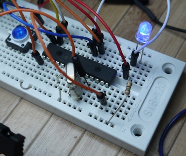
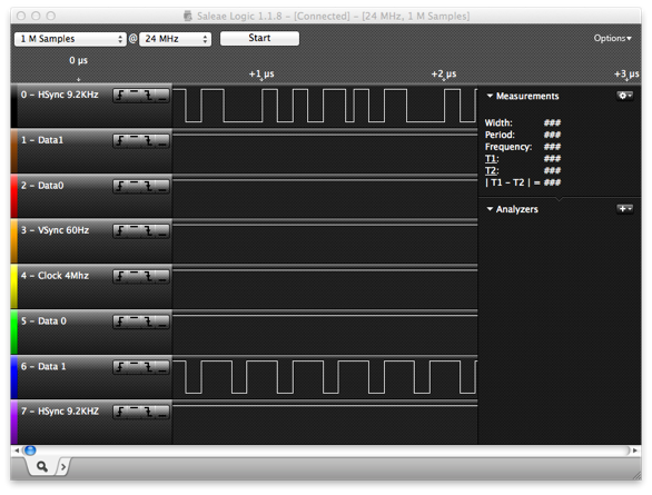
I’m using a PIC18F2550 for these experiments and programming in swordfish basic (my IDE of choice!). To help in the process, I am using the excellent Saleae Logic Analyser (man these things are great!)
I’m using a PIC18F2550 for these experiments and programming in swordfish basic (my IDE of choice!). To help in the process, I am using the excellent Saleae Logic Analyser (man these things are great!)

The 18F2550 Datasheet
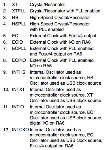
Of course everyone reads their datasheets when venturing into any electronic project! Well that is, until you can’t get it to work without the datasheet… Anywho, here’s a copy and paste of the available oscillator configs for the 18F2550.
I won’t be using the internal oscillator for these tests so I’ll be ignoring all of the INT modes.
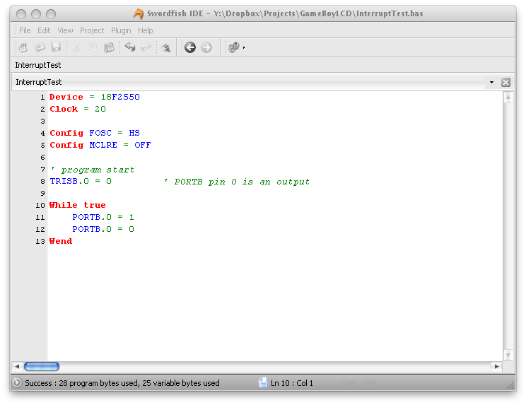
First Test – 20Mhz Oscillator no PLL
The code simply sets it up for using a 20Mhz clock, sets PORTB.0 as an output and then makes it high, then low and loops back around. The Config FOSC = HS simply means we are using a High Speed oscillator (20Mhz falls into this category).
Checking the output we can see that it is high for 0.2083uS (208.3nS) and then low for a whole heap longer – 583.4nS.
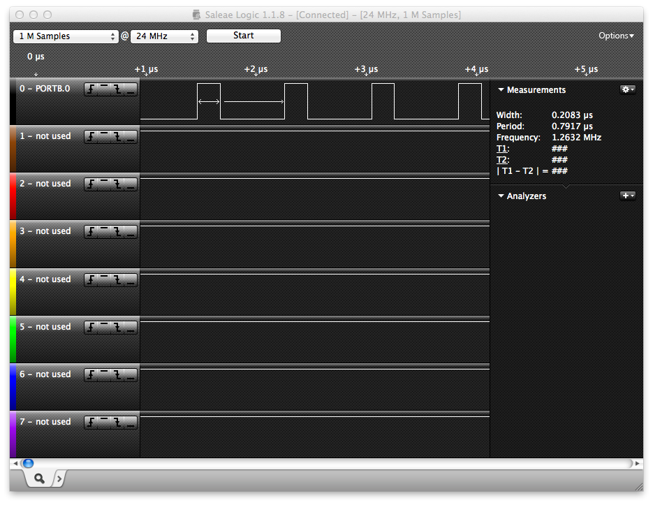
Does this line up with what we would expect? The datasheet tells us that for a 20Mhz clock, we are going to get 5MIPS (Million Instructions Per Second) we simply need to divide the clock by 4 to get our speed in MIPS.
So therefor each instruction should take 1 / 5,000,000 = 200nS which is pretty good because from the time PORTB.0 went high, to when it went low again it was very close to 200nS at 208.3nS. Not bad!
But shouldn’t it stay off for just as long you might be asking? Well no. that’s because it stays off while the code loops back around to the start of the WHILE WEND loop. so we make it low, it stays low for probably 208.3nS then it takes time to loop back around to where it has the instruction to go high again. So therefor it takes:
583.4nS – 208.3nS = 375.1nS for the WHILE WEND loop to loop back around. Interesting 🙂
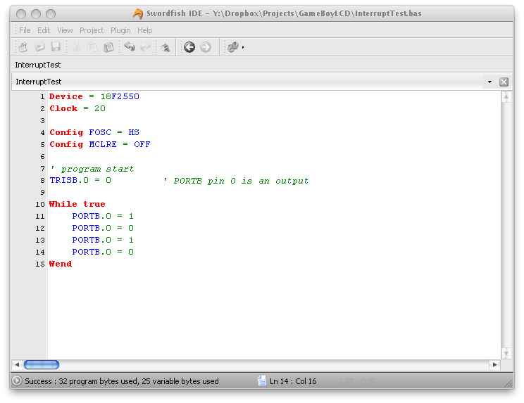
Let’s double check by copying and pasting the code to turn the LED’s on then off:
And here’s the output:
Well, it seems that we were correct! by adding and extra on, then off cycle before looping, we can see that PORTB.0 does infact stay off for as long as it was on – then it stays off for a long time while we loop back to the start of the WHILE WEND loop.
Second Test – 20Mhz Oscillator with PLL
Let’s just check that this PLL (Phase Locked Loop) is all it’s cracked up to be Apparently we can max this thing out at 48MHz. The 18F2550 is USB 2.0 compatible and features a PLL that outputs 96MHz when the input to the PLL is 4Mhz. This 96MHz is divided by 2 to give 48MHz and is fed to the USB circuitry:
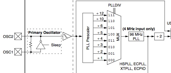
But since we’re using a 20Mhz oscillator, we need to reduce the frequency down to 4MHz, we do this with the help of the PLL Pre-scaler which is really just a fancy name for a frequency divider. In this particular pre-scaler we have eight different outputs (as seen above) so with our 20MHz oscillator, we have:
- 20MHz / 1 = 20MHz
- 20MHz / 2 = 10MHz
- 20MHz / 3 = 6.67MHz
- 20MHz / 4 = 5Mhz
- 20MHz / 5 = 4MHz
- 20MHz / 6 = 3.33MHz
- 20MHz / 10 = 2MHz
- 20MHz / 12 = 1.67MHz
Can you guess which one of these frequencies we need to feed into the PLL? That’s right! The bold one! So we add this line of code to allow the divide by 5 (which is 4MHz) frequency through the multiplexer (MUX) and onto the input of the 96MHz PLL.
Config PLLDIV = 5
Okay that’s all well and good for the USB side of things, but we want our microcontroller code to also get in on this 48MHz action. This 96MHz gets fed down to another scaler which is the PLL postscaler:
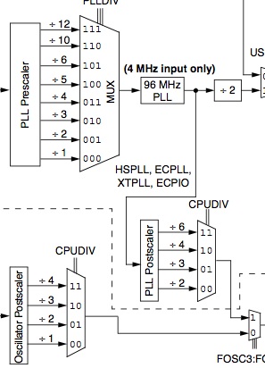
The postscaler then divides our 96MHz up into:
- 96MHz / 2 = 48MHz
- 96MHz / 3 = 32MHz
- 96MHz / 4 = 24MHz
- 96MHz / 6 = 16MHz
Pretty simple to see which one we need to achieve our max clock speed of 48MHz… We need to divide by 2! We do this by adding this line of code:
Config CPUDIV = OSC1_PLL2
This will now feed 96MHz / 2 = 48MHz through the CPUDIV MUX and onto our CPU. So now let’s run the same test as before to see how long each instruction takes… Here’s the full code (notice the two new lines which have set up the PLL):

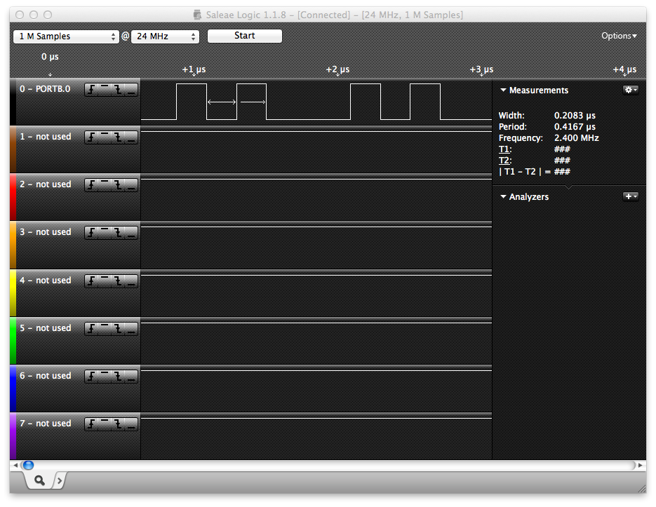
And here’s the output:
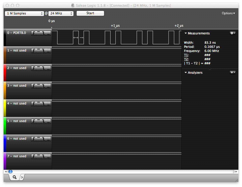
Well what do you know! it’s running a whole heap faster than before we enabled PLL. But let’s see if this 48MHz is all it’s claiming to be shall we.
You can see the clock pulse goes high and then stays high for 83.3nS before the PORTB.0 = 0 instruction comes into play. so therefor, 1 instruction is taking 83.3nS. Does this line up though? if we had a clock of 48MHz, to get MIPS we just need to divide by 4 so 48MHz / 4 = 12MIPS.
So we should be getting 12 Million instructions per second out of this thing. How long should each instruction take then?
Well, 1 / 12MIPS = 83nS
Excellent! looks like everything is panning out. Now I can continue on with my VGA projects 🙂
I hope this little tid bit of information has helped you out, I know that documenting it like this will help me in the future (especially if I keep documenting all my little experiments).
God bless and I hope you have a huge amount of fun with your electronic projects.


[…] Microcontroller Oscillator Experiments | {Brads Electronic Projects} https://www.bradsprojects.com/Tonight I decided to do a few experiments with an 18F2550 and PLL settings to see exactly what effect it would have on the operation of the microcontroller. More specifically, I just wanted to fix firmly in my head what the data … […]