Im going to try and explain which pin does what on the matrix and hopefully from that it will help people with any connection problems.
The picture below is a picture of one side of the 8x8 matrix.
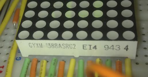
- 8x8_matrixside.jpg (18.96 KiB) Viewed 72606 times
You will see the manufacturing codes on one side of the 8x8 matrix something like the picture above (if you obtained them from Sure Electronics)
I am starting with this because this is our starting point for the 8x8 matrix, this tells us which way the display should be positioned. So the 8x8 matrix should be positioned with the manufacturing code on the left while looking at the top of the matrix. for example the picture below:
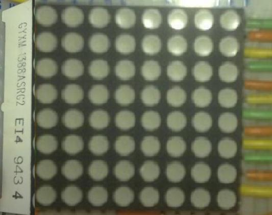
- side of matrix.jpg (25.24 KiB) Viewed 72606 times
Now we move onto which pin connection does what on the matrix, the best way I found I could explain it is by the picture below using ROWS and COLUMNS:
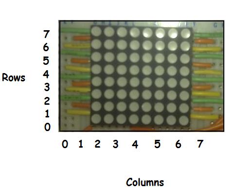
- 8x8matrix2.jpg (19.57 KiB) Viewed 72606 times
Starting with the picture above of the top of the matrix, on the left bottom of the matrix you see a yellow wire going to the matrix, then above that an orange and then above that a green wire and then it repeats again, yellow, orange, green and so on, the same goes for the right side of the matrix, starting at the bottom yellow, orange, green and so on.
The wire colours indicate which pin is what.
for example:
Yellow wire = POWER SUPPLY (ANODE)
Orange wire = RED CATHODE
Green wire = GREEN CATHODE
In the picture above you will also see we have ROWS on the left and COLUMNS on the bottom with the numbers 0.. 1.. 2.. 3.. to 7.. if you imagine the bottom ROW of leds of the matrix as ROW-0.. and the TOP ROW of leds as ROW-7, and then we have the COLUMNS so if you imagine the LEFTMOST column has COLUMN-0 and the RIGHTMOST column has COLUMN-7..
So the yellow wire on the bottom left of the matrix is a power supply (ANODE), this is a power supply for LEFTMOST COLUMN (COLUMN-0), the yellow wire above that is a power supply for COLUMN-1, the yellow wire above that is a power supply for COLUMN-2 and the last yellow wire on the top left is a power supply for COLUMN-3, the other side of the matrix (right side) bottom yellow wire is a power supply for COLUMN-4, next yellow one up is for COLUMN-5, then yellow one above that is for COLUMN-6 and the last top yellow wire is a power supply for COLUMN-7.
So bottom left orange wire and green wire are the CATHODES for RED and GREEN on the bottom ROW which is bottom ROW-0, the orange and green wires above that are for ROW-1, ones above that are for ROW-2 and the last orange and green wires on the top left are for ROW-3. going over to the right side of the matrix on the bottom, orange and green wires are the CATHODES for RED and GREEN leds again but these are for ROW-4, next ones up are for ROW-5 and next ones up above that are for ROW-6 and the top right orange and green wires are for ROW-7 the top ROW of leds on the matrix.
I hope this has been easy enough for anyone to understand

